
Analog Electronics deals with electronic systems that has a continuous variable signal. In this section we will discuss about various analog electronic projects that can be used to design your own amplifiers, oscillators, filters, analog converters, waveform generators and other analog circuits as required by your application.

Dancing LEDs circuit is used for decorative purpose and looks very good when these LEDs glow in sequential manner. We can create many kind of Dancing LEDs patterns for decoration. In this particular circuit, we have created a pattern in which 6 LEDs are illuminating in forward and reverse order. To create this circuit we have mainly used 555 timer IC and 4017 IC.
…
In this project, we are going to make a day and night indicator (or dark and light indicator) which will indicate if there is a dark or light in the surroundings. Some applications of this circuit, are street light controlling, home/office light controlling, day and night indicators, etc.
Components Required IC LM358 -1 150 Ohm…

This car parking assistant can protect your car from any damage while reverse parking. It indicates the distance of car from any object and raise an alarm when it reaches close to the wall or the object and needs to be stopped. This car parking sensor circuit is quite easy and uses few commonly available components which are listed below.
…
Sometimes we face a common problem when making any project related to battery or power supply - we don’t know about battery is charged or discharged. To test battery there is one common method which is using voltmeter that is available in the Multimeters. But here we have developed this battery monitor circuit to test the battery charging status. In…

Electronic clock with LED pendulum & tick tock sound produces Tick Tock sound every second and it has a LED pendulum in which 6 LED glow in forward and reverse sequence like a Pendulum, each LED glow in one second. This circuit is very useful and inexpensive. You can build your own clock which can be used in many applications like toys, robots etc. To create…
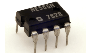
555 Timer IC is one of the commonly used IC among students and hobbyists. There are a lot of applications of this IC, mostly used as vibrators like, ASTABLE MULTIVIBRATOR, MONOSTABLE MULTIVIBRATOR, and BISTABLE MULTIVIBRATOR. You can find here some circuits based on 5555 IC. This tutorial covers different aspects of 555 Timer IC and explains its working in…

Thermometers are useful apparatus that have been used for a long time for temperature measurement. In this project, we have made an Arduino based digital thermometer to display the current ambient temperature on a 16x2 LCD unit in real time. It can be deployed in houses, offices, industries, etc., to measure the temperature. We can divide this Arduino…

Clap switch is an interesting hobby circuit that turns on the lights with a clap sound. Although its name is “Clap switch”, it can be turned ON by any sound of approximately the same pitch as a clap. The main component of this clap switch circuit is the Electric Condenser Mic, which has been used as a sound sensor. The Condenser Mic basically converts sound energy into…

Fire alarms are a prime necessity in modern buildings and architecture, especially in banks, data centres, and gas stations. They detect fire in the ambience at a very early stage by sensing smoke or heat and raise an alarm, which warns people and gives them sufficient time to take preventive measures. It not only prevents big losses caused by deadly fire but sometimes…

Water tank overflow is a common problem which leads to the wastage of water. Though there are many solutions, like ball valves which automatically stop water flow once the tank gets full, electronics enthusiasts prefer smart electronic solutions. This comprehensive water level indicator project tutorial will guide you to build a simple DIY water level indicator circuit that…

In electronics most commonly failed component is transistor. To test the working of the transistor, one must go through a lot of testing though multimeter. By testing one terminal after another, this consumes a lot of time and also this option is no good for newbies. The transistor testing circuits which are present already are complex to understand and design. In this…

Technically stepper motor driver circuit is a Decade Binary Counter circuit. The advantage of this circuit is, it can be used to drive stepper motors having 2-10 steps. Before going any further, let’s discuss more about the basics of a stepper motor.
Table of Contents What is a Stepper Motor Driver Circuit? └ Key Benefits…