

Technically stepper motor driver circuit is a Decade Binary Counter circuit. The advantage of this circuit is, it can be used to drive stepper motors having 2-10 steps. Before going any further, let’s discuss more about the basics of a stepper motor.
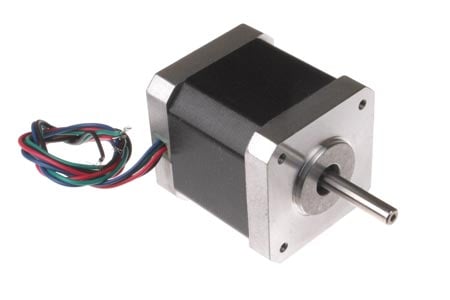
Table of Contents
What is a Stepper Motor Driver Circuit?
A stepper motor driver circuit is essentially a decade binary counter circuit designed to control stepper motors with precision. The name of this motor is given because the rotation of the shaft is in step form, which is different from DC or any other motor. In other motors, the speed of rotation, the stop angle are not in complete control unless a necessary circuit is inserted. This non-control is present because moment of inertia, which is simply a characteristic to start and stop on command without delay. Consider a DC motor; once it's powered, the speed of the motor increases slowly until it reaches the rated speed. Now, if a load is put on the motor, the speed decreases below the rated and if the load is further increased, the speed further decreases. Now, if the power is turned off, the motor does not come to a halt immediately, as it will have a moment of inertia, and it stops slowly. Now, we consider this a case in a printer; the paper outflow does not stop in time, and we lose paper every time we start and stop. We need to wait for the motor to pick the speed and due time, and the paper is lost. This is unacceptable for most of the control systems, so to solve this kind of problem, we use stepper motors. The stepper motor driver's working principle involves converting continuous clock signals into sequential pulses that energise the motor windings in a specific order.
Key Benefits of Stepper Motor Drivers
Very precise position control without feedback
High torque at low speeds
Great holding torque when static
It's compatible with digital control
No brushes, so this will last longer
Types of Stepper Motors and Driver Compatibility
The stepper motor does not work on a constant supply. It can only be worked on with controlled and ordered power pulses. Before going any further, we need to talk about UNIPOLAR and BIPOLAR stepper motors. As shown in the figure, in a UNIPOLAR stepper motor, we can take the center tapping of both the phase windings for a common ground or for a common power. In the first case, we can take black and white as a common ground or power. In case 2, black is taken for a common. In case 3, orange, black, red yellow all come together for a common ground or power.
In a bipolar stepper motor, we have phase ends and no center taps, and so we will have only four terminals. The driving of this type of stepper motor is different and complex, and the driving circuit cannot be easily designed without a microcontroller.
The circuit which we designed here can only be used for stepper motors of UNIPOLAR type. Compatible with basic stepper motor driver modules
The pulsing of the UNIPOLAR stepper motor will be discussed in the circuit explanation.
Unipolar vs Bipolar Stepper Motors
| Motor Type | Wires | Driver Complexity | Torque Output | Circuit Cost |
| Unipolar | 5-8 | Simple | Moderate | Low |
| Bipolar | 4 | Complex | High | Higher |
Essential Components for Stepper Motor Driver Circuit
- +9 to +12 supply voltage
- 555 IC
- 1KΩ, 2K2Ω resistors
- 220KΩ pot or variable resistor
- 1µF capacitor, 100µF capacitor (not compulsory, connected in parallel to power)
- 2N3904 or 2N2222 (no. of pieces depends on the type of stepper; if it’s a 2-stage, we need 2; if it’s a four-stage, we need four)
- 1N4007 (no. of diodes is equal to no. of transistors)
- CD4017 IC.
Stepper Motor Driver Circuit Diagram and Explanation
The stepper motor driver circuit diagram shows the interconnection

The figure shows the circuit diagram of a two-stage stepper motor driver. Now, as shown in the circuit diagram, the 555 circuit here is to generate a clock or a square wave. The frequency of clock generation in this case cannot be kept constant, so we need to get a variable speed for the stepper motor. To get this variable speed, a pot or a preset is placed in series with a 1K resistor in a branch between the 6th and 7th pins. As the pot is varied, the resistance in the branch changes, and so the frequency of the clock generated by the 555.
Two-Stage Stepper Motor Driver Circuit
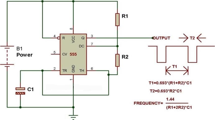
In the figure, the important thing is only the third formula. You can see that the frequency is inversely related to R2 (which is 1K+220k POT in the circuit). So if R2 increases, the frequency decreases. And so if the pot is adjusted to increase the resistance in the branch, the frequency of the clock decreases.
The clock generated by the 555 timer is fed to the DECADE BINARY counter. Now the decade binary counter counts the number of pulses fed at the clock and lets the corresponding pin output go high. For example, if the event count is 2, then the Q1 pin of the counter will be high, and if is 6 count the Q5 pin will be high. This is similar to a binary counter; however, the counting will be in decimal (ie, 1 2 3 4 __ 9), so if the count is seven, only the Q6 pin will be high. In the binary counter Q0, Q1 and Q2 (1+2+4) pins will be high. These outputs are fed to the transistor to drive the stepper motor in an orderly way.
Four-Stage Stepper Motor Driver Circuit

In the figure, we are seeing a four-stage stepper motor driver circuit very similar to the two-stage one. In this circuit, it can be observed that the RESET connected to Q2 before is now moved to Q4, and the opened Q2 and Q3 pins are connected to another two transistors to get a four-pulse driving set to run the four-stage stepper motor. So it is clear that we can drive up to a two-stage stepper motor. However, one should move the RESET pin up to fit in driving transistors in place.
The diodes placed here are to protect the transistors from inductive spiking of the stepper motor winding. If these are not placed, one might risk blowing the transistors. The greater the frequency of pulses, the greater the chance of blowup without diodes.
Stepper Motor Driver Working Principle
For a better understanding of the step rotation of a stepper motor, we are considering a four-stage stepper motor as shown in the figure. The stepper motor driver working principle follows this sequence:
Now consider, for example, all coils are magnetised at a time. The rotor experiences forces of equal magnitude from all around it, and so it does not move. Because all are of equal magnitude and are expressing opposite directions. Now, if the coil D is only magnetised, the teeth 1 on the rotor experience an attractive force towards +D and the teeth 5 of the rotor experience a repulsive force opposing the –D. These two forces represent an additive force clockwise. So the rotor moves to complete a step. After that, it stops for the next coil to energise to complete the next step. This goes on until the four steps are complete. For the rotor to rotate, this cycle of pulsing must be going on.
As explained before, the preset is set to a value for a certain frequency of pulses. This clock is fed to the decade counter to get regular outputs from it. The outputs from the decade counter are given to transistors to drive the high-power coils of the stepper motor in sequential order. The tricky part is, once a sequence is complete, say 1, 2, 3, 4, the stepper motor completes four steps, and so it is ready to start again; however, the counter has a capacity to go for 10, and so it goes on without interruption. If this happens, the stepper motor must wait till the counter completes its cycle of 10, which is not acceptable. This is regulated by connecting RESET to Q4, so when the counter goes for five counts, it resets itself and starts from one, which starts the sequence of the stepper.
Reset Configuration for Different Motor Types
| Motor Steps | Reset Pin Connection | Sequence Length | Application |
| 2-step | Q2 | 1-2-1-2 | Simple positioning |
| 4-step | Q4 | 1-2-3-4 | Standard applications |
| 6-step | Q6 | 1-2-3-4-5-6 | Higher resolution |
| 8-step | Q8 | 1-2-3-4-5-6-7-8 | Precision control |
FAQs About Stepper Motor Drivers
⇥ 1. What is the difference between unipolar and bipolar stepper motor drivers?
Unipolar drivers operate by cutting power to one-half of the coil, requiring center-tapped windings (think 4 wires instead of 2). Unipolar drivers are fairly simple and utilise simpler control circuits: the current must always flow in one direction without the need for an H-bridge. Bipolar drivers have H-bridge circuits to produce current in either direction; however, their more complex circuitry produces greater overall torque but requires somewhat more complicated control electronics.
⇥ 2. How do I calculate what the current rating for my stepper motor driver should be?
Look in the motor datasheet for the rated current per phase. With that number, you should have a driver that performs as expected if it is authorised at least 120-150% of the current rating to allow for safety margins, as well as for the initial interest current when stepping.
⇥ 3. Why does my stepper motor vibrate or make noise during operation?
Vibration is common secondary to resonance at certain frequencies, or issues with the power supply, mechanical coupling issues with motor mounts or bearings. You can typically reduce vibration and noise by adjusting speed, adding damping, or microstepping.
⇥ 4. Can the same driver circuit be used with stepper motors with different numbers of step counts?
Yes, provided that the reset pin connection to the CD4017 counter is deleted or modified. For 2-step motors, tie reset to Q2; for 4-step motors, tie reset to Q4; for 6-step motors, tie reset to Q6. You can employ the same driver circuit on different step-count motors.
⇥ 5. What happens if I do not use protection diodes in my stepper motor driver?
Without the protection diodes, voltage spikes caused by the inductances in the motor windings can potentially damage the transistors; this becomes more severe at higher switching frequencies. It is the flyback diodes that protect the transistors from damage and ensure correct operation in every stepper driver circuit.
⇥ 6. How do I control the direction of rotation in a stepper motor driver circuit?
Include direction control by reversing the order of the sequence using extra logic gates, by using an up/down counter such as CD4029, or by actually reversing two of the motor winding connections via switching circuits.
So this is how the stepper continues its stepping, and so the rotation happens. For a two-stage design, the RESET pin must be connected to Q2 for the counter to reset itself in the third pulse. This way, one can adjust the circuit to drive a ten-step stepper motor.
Discover Stepper Motor-Based Projects
Many compelling projects have been crafted with the Stepper Motor see the links below for more.

Stepper Motor Control with A4988 Stepper Motor Driver and Arduino UNO
In this A4988 stepper motor driver tutorial, we'll be looking at how to interface and connect the A4988 stepper motor driver module Arduino and go over the basic principles of stepper motors, A4988 stepper motor driver pinout, wiring connections, and programming examples.

Wireless Stepper Motor Controller with ESP32 and TMC2240
This tutorial presents an innovative solution for remote stepper motor control, allowing you to precisely adjust its position, track its performance, and receive real-time feedback from a simple web browser.

Interfacing TMC2209 Stepper Motor Driver with Arduino UNO – Basic Direction and Stepping Control
This stepper motor driver guide is perfect for beginners looking to learn Arduino stepper motor control using digital signals to move motors forward and backwards with exceptional precision.
Comments
It is well explained and helpful
How do you reverse step motor rotation direction with this circuit ?
Lionel, to reverse the direction you have to reverse the count, at present it counts UP so you need to make it count DOWN so a different counter chip would be needed, one where the count direction can be switched, search for UP DOWN COUNTER IC in Mr Google.
Peter
Your Part List shows the need for a IN4047 diode. Is this a typo? Shouldn't it match the schematic and say IN4007? I looked up that part number, surprisingly, it exists, though not a diode. Digi-Key carries it and it's not cheap($52 US), I would hate to have a newbie order four of them to finish this circuit. All that aside, thanks for putting this together.
Hello,
I'm building an astro tracker and i'm using this:
banggood.com/JKM-42-Linear-Stepper-Motor-Trapezoidal-Screw-320MM-0_32NM-p-933434.html
I read your article and I saw that it's complicated... so do i absolutely have to use an arduino board?
Or would you have something i could use with a couple of 555 timers... and a variable resistor?
Thanks,
Reuben
Very well explained and congratulations.
very nice video....& nice diagram in simple..thanks a lot
Can you set up the circuit to stop after 4 stages or one rotation?
What type of stepper motor should I use? 4-phase, bipolar or unipolar? The one which is simpler to construct and use?
hi! can i ask if that motor can reverse also by calibrating that vr!? or it moving by one direction only?
what kind of stepper motor uve used in that circuit!?
Can you provide me with the schematic thank you . Alberto
I wish it was available in a pre-wired circuit-board where we could just swap out resistors. Frankly speaking, I'm surprised that doesn't exist as it seems like it would be a good seller.
Great tutorial. My stepper motors come with a little ULN2003 interface board. Looking at the specs for the ULN2003 I am guessing that I can use it in place of the output transistors and diodes in your schematic (i.e. hook the output pins of the CD4017 to the input pins of the ULN2003.) Is it that simple or would I need other components?
Hi, I constructed the circuit as per your instructions above, only substituting a ULN2003 driver board that came with the 28byj-48 motor for the four output diodes in the schematic. The LEDs on the driver board seem to indicate that the driver lines are being energized in the correct sequence, but the motor doesn't turn, it just clicks or vibrates. I read somewhere that the sequence to cleanly rotate the motor should be A-AB-B-BC-C-CD-D-DA, so I modified your circuit to use 8 of the decade counter outputs to generate the above sequence, by using each odd numbered counter output to drive two motor driver lines, and with diodes to prevent unwanted shorts. Again the driver board LEDs show what appears to be the correct sequence, but the motor still just vibrates.
I know that the motor is not defective as I have tested it with an Arduino, using very basic I/O output (i.e. not using any stepper library code) to generate the above sequence and it works just fine. In this configuration the motor is powered seperately by the same 5V power supply that I'm using to power the decade counter circuit, the Arduino itself is powered by USB.
I was really hoping to eliminate the Arduino, as my requirement is for very simple constant slow rotation and the Arduino seems to be overkill for that purpose.
Do you or anyone else have any idea why the motor isn't rotating?
Update: I found the cause of the problem, and it is exactly what many people have said online - incorrect motor wiring. I was connecting the output lines in the wrong order(IN1-IN4). When I reversed the order (IN4-IN1) the motor rotates as expected, and without the need for the extra 'dual' coil activations.

Nice one