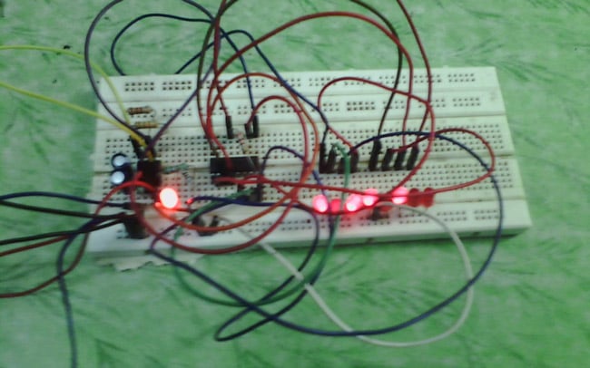
For an electronics hobbyist or a student 555 timer IC is one of the most important electronic components because of its functioning flexibility. One can develop different kinds of circuits using this IC. Here we are discussing a simple circuit using 555 timer IC as an ASTABLE MULTIVIBRATOR. This circuit make an LED blink for every half second, and the square wave output of 555 IC is connected to a BINARY counter of 8bit (74HC4040). Each time when a pulse is generated by timer, binary counter counts it and stores the value. More about the working of this circuit is discussed in subsequent sections.
Circuit Components
Power supply (5v)
47uF capacitor
220, 1K, 10K resistors
555TIMER IC
HD74HC4040 Binary counter IC
9 LEDS
Connecting wires and breadboard
Circuit Diagram
The circuit design basically starts with 555IC square wave generation. Once all the components are placed according to the schematic diagram above, the “LED1” must be blinking at a rate of half a second. For changing speed of blinking of LED one can change the capacitor, higher the value of capacitor lower the speed of blinking. However choosing a capacitance over 100uF is not good and below 4.7uF is also not suggested. Over 100uF the frequency of blinking slows considerably and one might mistaken it as a failure circuit, and if chosen lower capacitance the blinking would be too fast for the human eye to catch and may be presumed as a failure. And so it is well advised to keep the capacitance value in check while choosing a capacitor. The binary counter has a capability to drive the LED directly so there is no need for resistors at the end of binary counter's LEDS. The MR (Master Reset ) of binary counter must be pulled down at any time, leaving it open might cause unpredictable results at the LEDS might blink randomly.
Working
Square wave generation happens at the trigger terminal (2nd PIN) of 555IC. When the power supply is turned ON then at the very beginning the capacitor starts storing the charge and so the potential across the capacitor increases so to trigger the IC and pushing it into ON. After a certain time the capacitor gets enough potential to discharge through R2. At this point the IC output is turned to OFF state and it stays at OFF until capacitor starts charging again. And so we have square wave at the output.
Now the square wave output of 555IC is fed into counter as clock, so every time a peak is passed the counter considers it as an event and increments the output by one for every passing event. Once it reaches its limit to track the events, it automatically resets to zero and starts again to count the pulses. And for the output it provides the event number as binary output through pins 9,7,6,5,3,2,4,13,12,14,15,1. In LSB to MSB manner. So if the event count is 10 the pins (7(2^1=2),5(2^3=8)) will be high and so the corresponding LEDS glow. To reset the counter to zero under any stage connect the MR pin of counter to +5V, this resets the counter to zero.
Common Errors
The LED connected with the 555 IC is not blinking:
- Check the power at the 8th and 1st pin with a multimeter, it should be between 5v and 15v.
- Check for capacitor terminal placement (negative to ground ).
- Check the value of capacitor on label of capacitor. Better keep the capacitance between 4.7uf to 100uf.
- Check the LED to blink.
- Check the ground of LED.
- Touch the IC to check the temperature; if it’s hot reconnect the circuit and is still hot replace the IC.
LED is just ON:
- Check the capacitor.
- Check the connections.
LEDs at the counter end blinking randomly:
- MR should be pulled down.
LEDs at the counter end not blinking:
- Clock provided by 555 timer might not have been sufficient, remove the LED connected at 555 timer output.
- Check the power of counter at 16th pin and at 8th pin.
- Touch the IC to check the temperature; if it is hot reconnect the circuit and if still it is hot, replace the IC.


