At electronica India 2026, Nitin Jain, co-founder of 1Buy.AI, sat down with Aswinth Raj, editor of CircuitDigest, for an episode of electronica Xchange to discuss the role of artificial intelligence in procurement and its impact on India's supply chain.
CP PLUS, the surveillance brand under Aditya Infotech, traces its origins to 2007. That year, the company decided to enter the surveillance technology space, with a vision of CCTV cameras becoming commonplace across India. What was then considered a luxury item for select businesses has since become, as M.A. Johar, President of Strategic Business at CP PLUS, put it, "a necessity" for hotels, small shops, and large projects alike.
We're all familiar with live GPS tracking; it tells us where a vehicle or device is right now. But what if the system could do more than just show the location? That's where geofencing using IoT comes in. Imagine receiving an instant alert the moment a vehicle leaves home, reaches college, enters the office, or moves into a restricted area. Instead of repeatedly checking a map, the system itself notifies you whenever something important happens. Think about it: if you're tracking a vehicle, do you really want to keep opening the app and checking its location every few minutes? Most of the time, you only care about specific places and important events. For example, you might want to know when a vehicle reaches college, leaves the office, arrives home, or enters an area that is restricted. Rather than watching the location all day, it would be much easier if the system could automatically inform you whenever these events occur. In this project, we build a complete IoT geofencing system using the GeoLinker GL868_ESP32 board: an ESP32-S3 paired with a SIM868 GSM modem. That's exactly what geofencing helps us do. It allows us to create virtual boundaries around important locations and detect when a device enters or leaves them. By combining geofencing with live GPS tracking, we can build a smarter location-monitoring system that not only tracks a device but also keeps users informed at the right time. Let's dive in and see how to do that. Before that, visit the GeoLinker wikipage to learn about the full spec and get to know the full details of the GeoLinker.
The system begins by powering on the GeoLinker. Then the board will search for the SIM card and connect to the network, and then keep the board outside for a bit. This ensures the board connects to the satellite for the GPS. Before deploying the code to the board, you should configure multiple geofences by specifying the latitude, longitude, and radius of each zone. In this project, four geofences are created: Home, College, Office, and Restricted Area. Once initialization is complete, the GPS module continuously acquires the current location of the device. The obtained coordinates are then compared with the boundaries of all the configured geofences to determine whether the device is inside or outside each zone. The system continuously monitors the device's movement and checks for any change in geofence status. When the device enters a geofence area, the system detects the event and generates an alert. Similarly, when the device exits a geofence, another alert is generated. For normal zones such as Home, College, and Office, an SMS notification is sent to the registered mobile number whenever an entry or exit event occurs. These alerts help the user know the movement of the tracked device in real time. A separate geofence is created for the Restricted Area. Whenever the device enters or exits this zone, the system sends an SMS notification and additionally triggers an automatic phone call. The phone call ensures that critical security-related alerts receive immediate attention and are not missed by the user. The device periodically uploads its location and signal strength to the CircuitDigest Cloud every 30 seconds, enabling real-time tracking and remote monitoring through the dashboard. This allows the user to view the device's live location and status remotely through the cloud dashboard.
*Note: Not only these, but we also have several example codes like advanced tracking, call triggering, automatic sleep code, etc., which are available in the examples of the Arduino IDE. Spare some time and take a look at those worth exploring if you want to extend this IoT geofencing system project.
Component Requirements for IoT Geofencing System
The components below are the components which are essential ones used to make the geofencing alert system.
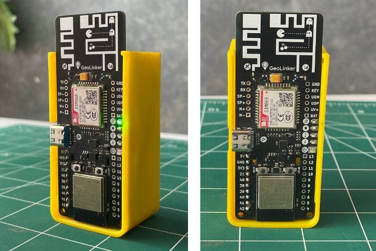
GeoLinker GL868_ESP32 is a production-ready, open-source development board that combines an ESP32-S3 and SIM868 GSM modem, used for tracking purposes.
-
2.
IoT / Normal Nano SIM Card
Airtel M2M IoT SIM recommended (3 months free data with board purchase). Any 2G-compatible SIM works.
Regular 2G SIM
3.
3.7V Li-Ion / LiPo Battery
Used for powering the board
LiPo pouch battery
4.
USB-C Cable
Programming, testing & charging
-
Hardware Configuration of Geofencing Using IoT
The hardware requirements for this system are minimal. Only the GeoLinker board and a battery are required for operation. The enclosure is optional and is used only for protection and improved appearance. Once the battery is connected to the GeoLinker board, the system automatically powers up and begins the initialisation process.
Code Explanation for the Multi-Geofencing System Using IoT
The code is written with the required libraries for GeoLinker and GPS. It also contains the sections where the coordinates need to be modified to ensure that geofencing works correctly according to the requirements. Different alerts are triggered based on the location. Additionally, the data is sent to the CircuitDigest Cloud at a specified interval.
This section contains all the important configuration settings used throughout the program. It defines the device ID, cloud API key, alert phone number, GPS timeout period, polling interval, and cloud upload interval. Keeping these values in one place makes the system easier to configure and maintain without modifying the main logic.
This section defines all the geofences used in the system. Each geofence contains a name, centre coordinates, radius, and alert type. The radius determines the size of the virtual boundary, while the restricted flag specifies whether the zone should generate only SMS alerts or both SMS and phone call alerts. All geofences are stored in an array, allowing the system to monitor multiple zones simultaneously. You should change the long and lat in the GeofenceZone zones[] section in the code for your requirements.
This function is responsible for obtaining the current GPS location from the GeoLinker module. The system continuously attempts to acquire a valid GPS fix within a specified timeout period. Multiple retries are performed to improve reliability in areas where satellite signals may be weak. Once a valid location is obtained, the coordinates are passed to the geofencing logic for further processing.
This section forms the core of the project. The system calculates the distance between the current GPS location and each geofence using the Haversine distance formula. The calculated distance is then compared with the geofence radius to determine whether the device is inside or outside the zone. Whenever the status changes, the system identifies it as an entry or exit event and prepares the corresponding alert.
This function is responsible for generating notifications whenever a geofence event occurs. A detailed alert message containing the event type and location information is first created and sent via SMS. If the geofence is marked as a restricted area, the system additionally schedules a phone call to the registered number.
*Note: A spoof code is also available in the GitHub repository, so you can go through it and test the system while sitting in one place.
Troubleshooting the GPS Geofence Alert System
The following are the problems that were faced while building the system and the different solutions that were used to overcome them. You can take a look at them and use these solutions if you encounter similar problems.
Problem
Cause
Solution
SMS alerts are not received
SIM card not registered on the GSM network or insufficient SMS balance
Check network registration status and ensure the SIM card has sufficient SMS balance and signal strength.
Phone call alert is not triggered for the Restricted Area
Incorrect phone number configuration or call service unavailable
Verify the alert phone number in the code and ensure the SIM card supports voice calling.
No GPS location is obtained
Weak GPS signal or indoor operation
Move the device outdoors with a clear view of the sky and wait for GPS satellites to lock.
Continuous false entry/exit alerts
GPS drift or geofence radius set too small
Increase the geofence radius and ensure GPS accuracy is sufficient for the application
System resets unexpectedly
Insufficient power supply during GSM transmission
Use a fully charged 3.7V Li-ion battery capable of supplying peak GSM current requirements
Device shows incorrect geofence status after restart
Previous geofence state not stored correctly
Verify NVS memory operation and ensure geofence states are saved properly before power loss.
The call is triggered, but not getting sms or vice versa
Maybe your number is not whitelisted.
Make sure to whitelist your registered number for the call and sms too.
Output Demo of the GPS Tracking System Using IoT
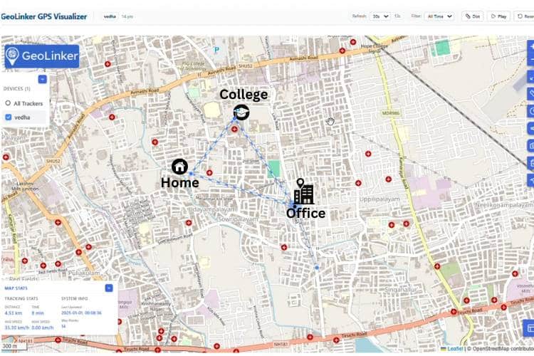
The live tracking of the GeoLinker board is shown below. The board continuously acquires its current GPS coordinates and transmits the location data to the Circuit Digest Cloud at intervals of 30 seconds.
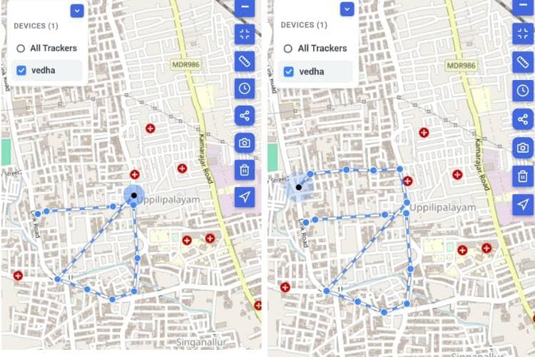
The figure below shows the virtual boundaries (geofences) that have been created for the system. The coordinates corresponding to these geofence areas are defined in the program code that was flashed into the GeoLinker board. These geofences represent specific locations, such as Home, College, Office, and Restricted Areas. Whenever the system enters or exits any of these predefined boundaries, the corresponding alerts are triggered automatically
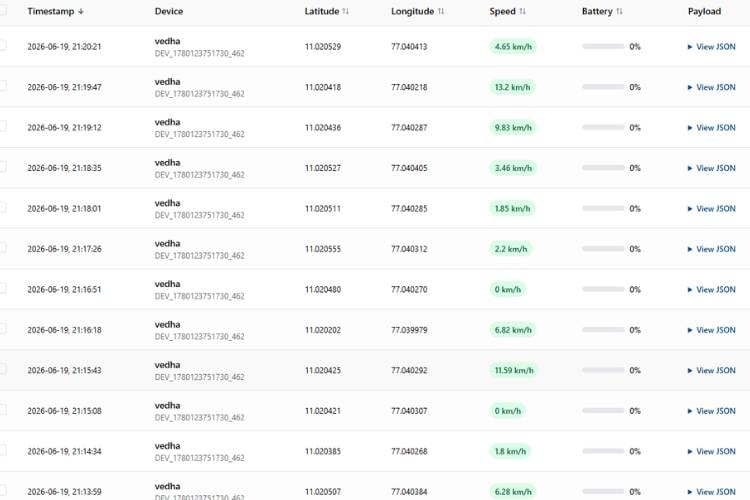
This screen displays the live tracking information received from the GeoLinker board. It includes important parameters such as the current date and time, latitude, longitude, speed, and battery percentage (when a battery is connected to the system). Additionally, the payload section contains further details transmitted by the device, providing comprehensive information about its status and location.
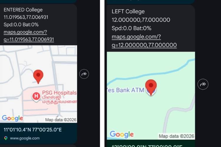
The figure below shows the entry and exit alerts generated for the different geofencing areas. Whenever the device enters or exits a predefined geofence, the system automatically sends an SMS notification to the registered user. The alert message includes the type of event (entry or exit), the name of the geofence area, and the live GPS coordinates of the device at that moment.
Additionally, if the device enters or exits a Restricted Area, the system generates an SMS alert similar to the alerts used for normal geofence zones. However, to ensure that critical notifications are not missed, the system also automatically places a phone call to the registered user. This dual-alert mechanism provides an additional layer of security by immediately drawing the user's attention to important events occurring within restricted zones. As a result, the user is informed through both SMS and voice call notifications whenever the device crosses the boundary of a Restricted Area. We also built an ESP32-based Interactive Voice Response (IVR) System using our GeoLinker board. Take a moment to see how it brings voice interaction and remote connectivity together
Live Working Demo of the Multi-Geofencing IoT System
Watch the Multi-Geofencing System in action as it detects and monitors multiple predefined geographic zones in real time using IoT technology. This live demo showcases accurate location tracking, instant geofence event detection, and seamless system performance.
Applications and Limitations of the Multi-Geofencing System Using IoT
The table below summarises the different applications of the proposed system and its limitations. Understanding these applications helps identify potential use cases, while the limitations provide insight into the factors that may affect the system's performance and reliability.
S.No
Applications
Limitations
1.
Fleet management for logistics and delivery services
Requires GPS signal availability for accurate location tracking
2.
Monitoring entry and exit of vehicles from homes, offices, and campuses
GPS performance may be affected in tunnels, underground areas, or dense urban environments
3.
Personal vehicle safety and anti-theft monitoring
SMS and call delivery may be delayed if network connectivity is poor
4.
Real-time location-based notification systems
Continuous GPS and GSM operation increases power consumption
5.
Restricted area monitoring and security applications
Requires periodic maintenance of the SIM card and data services
Conclusion for the IoT Geofencing System Project
In conclusion, this project shows how GPS tracking can be made more useful by adding geofencing capabilities. Instead of simply displaying the current location of a device, the system is able to recognise important location-based events and notify the user automatically. By creating multiple virtual boundaries and monitoring them continuously, this multi-geofencing system using IoT can detect when a device enters or exits specific zones and respond immediately. This system demonstrates the effective integration of GPS, GSM, cloud connectivity, and geofencing into a single system. It also highlights how automated alerts can reduce the need for constant manual monitoring. We also did an interesting project on parcel tracking. Feel free to check out our How to Build a Smart Parcel Tracking System Using IoT project.
IoT Geofencing System GitHub
Download the complete source code, circuit schematics, and project files to build your own IoT-based Multi-Geofencing System.
Frequently Asked Questions
⇥ How does the system know when a device enters or leaves a zone? The GPS location of the device is continuously compared with the coordinates and radius of each geofence. When the device crosses the boundary, an entry or exit event is detected.
⇥ Why is geofencing useful? Geofencing helps users receive automatic notifications based on location events instead of constantly checking the device's location on a map.
⇥ What happens when a geofence is crossed? The system automatically generates alerts. In this project, SMS notifications are sent for normal zones, while SMS and phone call alerts are generated for restricted areas.
⇥ Why is a phone call used in the restricted area? A phone call provides immediate attention and reduces the chance of missing an important security-related alert.
⇥ Can multiple geofences be created? Yes. The system supports multiple geofences such as Home, College, Office, and Restricted Area, and can monitor all of them simultaneously.
⇥ What technology is used to determine the location? The system uses GPS technology to obtain the real-time location of the device.
⇥ How often is location data uploaded to the cloud? The device uploads location data to the cloud every 30 seconds under normal operating conditions.
Related Raspberry Pi AI Projects Using CircuitDigest Cloud
Looking for more Raspberry Pi AI projects? Explore our CircuitDigest Cloud tutorials on Face Detection, Object Detection, and Helmet Detection. Each project includes detailed instructions, source code, hardware setup, and cloud-based AI implementation.
This project is based on the same concept, in which we have built a Raspberry Pi face detection system without any complex setup. We only need a Raspberry Pi, a USB camera, and an account in CircuitDigest Cloud.
That is exactly what this Raspberry Pi object detection project demonstrates. You can build a fully working object detection system on a Raspberry Pi without collecting a dataset, labelling images, or training any machine learning model.
So, what if there were a compact system that could make this task easier, provide accurate results, and reduce the burden on traffic police? That's exactly what this system does; here we used the Raspberry Pi, a powerful controller that can process data, analyse the images, and give the results instantly.
Modern server and data center design places increasing demands on the physical interconnect layer. At 112 Gbps and beyond, connectors are no longer treated as simple passive components; their design has a direct impact on crosstalk, impedance continuity, and mechanical integrity across the system. The following provides a technical overview of four Amphenol interconnect product families designed for high-speed data center and networking applications.
ExaMAX High-Speed Interconnect System
ExaMAX covers the 25 Gb/s to 56 Gb/s range, making it relevant for current-generation data center and AI infrastructure. Its beam-on-beam contact geometry is notable for two reasons: it avoids pin damage during mating, and it brings mating force down by 65% relative to blade-and-beam designs. The latter has practical consequences in dense backplanes where aggregate insertion force across hundreds of pins becomes a real mechanical concern.
Pitch options are 2 mm for density-constrained layouts and 3 mm where quad routing is preferred. The 3 mm option allows high-speed, low-speed, and power to share the same connector, which reduces PCB complexity and cost. The system spans a wide range of board architectures, including backplane, midplane, orthogonal, cabled, coplanar, and mezzanine, and is qualified against OIF, PCIe, SATA, Fibre Channel, InfiniBand, Ethernet, SAS, IBTA, and IEEE standards.
HD Express Interconnect System
Where ExaMAX is a general-purpose high-speed platform, HD Express is built around a specific target: PCIe Gen 6. The connector is optimized for 85-ohm systems and surrounds each differential pair's mating beams with ground shielding on all four sides. At Gen 6 signal speeds, that level of per-pair isolation is necessary to maintain acceptable crosstalk margins.
The modular single-wafer construction keeps costs manageable while making incremental system scaling straightforward. Press-fit termination is used throughout, which simplifies board assembly in server, storage, and supercomputer designs where soldering at this connector density would introduce process complexity.
AirMax VS Connectors
AirMax VS takes a different approach to isolation. Rather than surrounding differential pairs with metal shielding, it relies on air as the dielectric between adjacent conductors. The absence of metallic shields brings weight and cost down while the design still maintains signal integrity across the 12.5 Gb/s to 25 Gb/s range.
The family covers three generations: VS, VS2, and VSe. The VSe is the current performance tier, supporting 25 Gb/s with an open pin field design. Importantly, VSe is backward compatible with VS and VS2 footprints, so existing PCB layouts can be retained when upgrading. This makes the family practical for telecom, industrial, and storage applications where hardware longevity and multi-generation support are requirements rather than nice-to-haves.
XCede Backplane Connectors
XCede is designed for flexibility across both impedance and scale. It supports 85-ohm and 100-ohm configurations on the same mating interface with backward mate compatibility, and is available in 2, 3, 4, 5, and 6-pair variants supporting up to 82 differential pairs. That range accommodates deployments from small switching hardware up to large wireless infrastructure and external storage systems.
One cost-reduction feature worth noting is the availability of embedded capacitors within the connector body itself, which lowers overall system cost. The design also incorporates integrated power and guidance modules and is built for mechanical longevity in field-deployed hardware.
Availability
The above families represent four distinct approaches to high-speed interconnect design, each targeting different performance requirements, architectures, and application lifecycles. Detailed specifications, datasheets, and ordering information are available via the Mouser product links below.
This DIY tutorial is all about making our home lighting smart and fun without any complicated steps. We can connect a standard 12V LED strip to a tiny wi-fi chip and build our own ESP32 WLED controller custom smart lighting system, which can be completely controlled from a smartphone or computer.
This DIY ESP32 based WLED controller guide skips the days of writing complex coding lines to program the light patterns and goes with a ready-made, open-source software called WLED. Once we power on our physical build, the system automatically connects to our home Wi-Fi network; it's a DIY ESP32-WLED Controller Setup. You can also check out similar ESP32 Projects and IoT projects done previously here at Circuit Digest.
Quick answer: An ESP32 WLED controller is a DIY smart lighting driver that pairs an ESP32 microcontroller with the open-source WLED firmware to control addressable RGB (WS281X/CX2811A) LED strips over Wi-Fi, no coding required, controllable from a phone, browser, or Home Assistant.
Build type: ESP32-based WLED controller, no custom firmware coding needed
Control method: Wi-Fi (HTTP/JSON API), phone app, or web dashboard
In this project, we can send commands from a smartphone or the web dashboard of WLED to control the colours in addressable RGB lighting. When a user slides their fingers across the colour wheel, it sends the HTTP or JSON request over local Wi-Fi, which is intercepted by ESP32. Inside the ESP32, these Network packets are decoded and converted to digital data. WLED organises these data sequentially, 24 bits (red – 8 bits, green – 8 bits, blue – 8 bits) for every pixel in the group.
The ESP32 pushes this data out in 3.3V Digital Logic; the internal logical level shifter in the addressable RGB light converts the 3.3V logic to 5V logic. The first 24 bits received are stripped off to control the 3 physical LEDs connected by PWM (Pulse Width Modulation) to control their brightness. It also has a timer feature to turn off the addressable LED after an hour. The successive bits are regenerated and sent to the next chip. Here is the Voice-Controlled Smart Home Assistant project, where we showcased how voice recognition is incorporated with the RGB light.
Components Required for the ESP32 WLED Controller DIY Build
Below is the list of components required to build this ESP32 WLED controller project, with their descriptio
ESP32 WLED Controller Wiring Diagram and Schematic
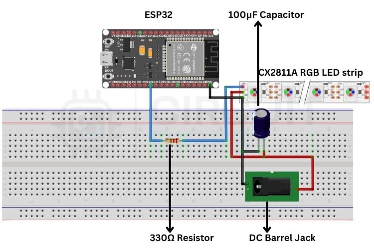
The schematic illustrates all the essential connections required to build the ESP32-powered WLED smart LED controller. Follow the wiring carefully to ensure stable power delivery and reliable wireless control of your addressable LED strip.
The ESP32 WLED controller Schematic setup is quite simple. From GPIO 16(RX2) 330Ω resistor is connected; the other end of the resistor is connected to the DIN of the CX2811A driver addressable RGB LEDs. The 100μF capacitor is placed between GND and +12V, and GND and +12V are given to CX2811A, addressing RGB LEDs. The GND of the ESP32 and the power supply are commonly grounded. You can also check out the Smart WLED Clock with RTC, PIR, Audio feedback and Environmental Monitoring project in CircuitDigest, which integrates addressable RGB LEDs with clock setup.
Step-by-Step ESP32 WLED Controller Setup Guide
The ESP32 WLED Controller setup process, step-by-step configuration, is listed below. This makes an unprogrammed ESP32 a fully automated smart lighting system.
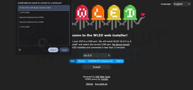
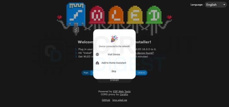
Step 1⇒Flash the WLED Firmware
Connect the ESP32 to the PC, open the https://install.wled.me/ website, click install, it shows many COM ports, select the CP2102 USB to UART bridge Controller (COM3) and click install. It will be installed. It will display a flash option to erase the ESP32 memory. Click erase, and it will be flashed and programmed for WLED.
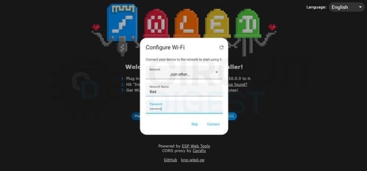
Step 2⇒ Configure the Wi-Fi Network
Then the Configure Wi-Fi menu opens, where you give your local Wi-Fi name and password and click Connect. The ESP32 will be connected to the Wi-Fi Network you entered. Double-check the network name and password. If it is not connected.
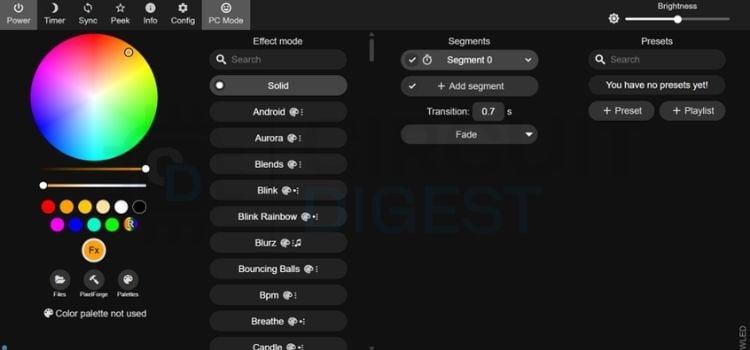
Step 3⇒ Access the WLED Web Dashboard
If the Wi-Fi is connected, the menu will open like Device connected to the network and click Visit Device to open the WLED Web Dash.
WLED Web Dash opens and shows menus to customise the RGB light, change Wi-Fi, adjust the Colour palette, set timer options, and sync with your Home Assistant, etc.
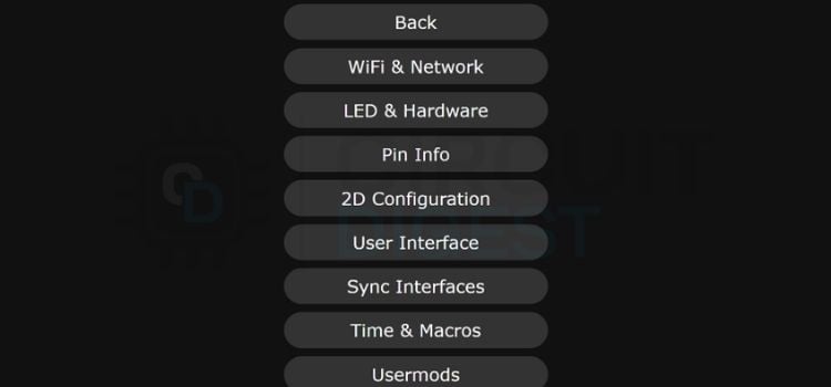
Step 4⇒ Open the Configuration Hub
Click the config tab at the top of the screen; it opens a menu from which we can able to change Wi-Fi, change hardware and software parameters, sync, and timer, etc.
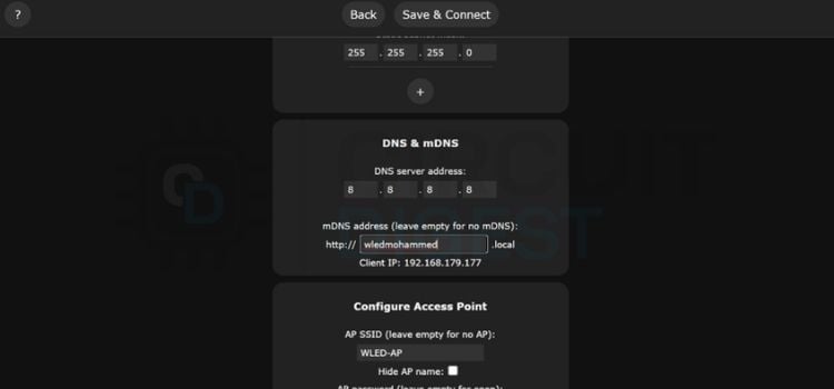
Step 5⇒ Set the mDNS Address
Click the Wi-Fi and Network tab. From there, we can change the mDNS address to any name you want to access the website, for example, the name it is set to is wledmohammed. From there, we can access our WLED through the name we set previously.
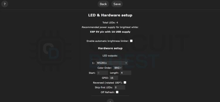
Step 6⇒ Configure LED and Hardware Settings
Click the LED and Hardware setup tab. Here, we need to change the type to WS281X, uncheck the Enable automatic brightness limiter, select the GPIO to 16 and select the number of LEDs you need to turn ON. These setups can also be done by Mobile Phone using the WLED application. If the strip light has 4 pins (V+, GND, DATA, CLK), choose APA102 or WS2801. If the strip has 5 pins (V+, R, G, B, W), choose PWM RGB. We can also able to choose the number of LEDs to glow.
Output
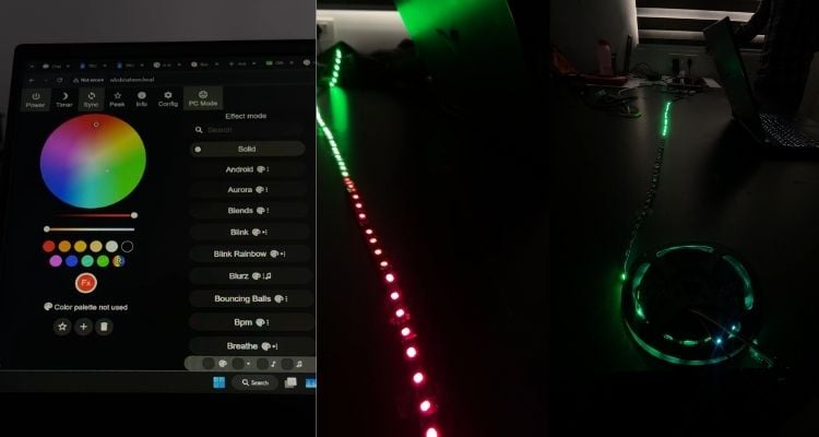
The Final physical circuit successfully powers the 12V addressable LED strip using the ESP32. When the ESP32 is turned ON, it hosts a WLED Web page. Where we can control the lighting of the strip using a colour Palette disc on a webpage, also by setting a timer function, we can be able to turn it OFF and ON at a preset time.
Live Demo: Smart Wi-Fi LED Controller with ESP32
Experience the real-time performance of the ESP32 WLED controller, showcasing wireless LED control, smooth animations, and smart lighting features.
ESP32 WLED Controller Manual: Troubleshooting Common Issues
Issue
Fix
How to properly ground the circuit?
The GND terminal of the RGB light and the 12V supply ground need to be connected to a common ground.
What power rating does the addressable RGB light need?
The CX2811A IC drives 3 Red, 3 Green, and 3 Blue LEDs together. Each LED draws 3.2V, totalling 9.6V; the remaining 2.4V is dropped internally/externally.
Selected colour doesn't match the strip's actual colour?
Change the colour order in the dashboard/app — try GBR, BGR, RBG, or BRG. BRG is the correct setting for most CX2811A strips.
ESP32 connects to the app, but the strip won't respond?
If using a phone hotspot for Wi-Fi credentials, turn off mobile data while the hotspot is on.
Real World Application:
∗ Smart Home Ambient Lighting: Integrated cove lighting for living rooms, false ceilings, and under-cabinet kitchen lights. ∗ Commercial Display Branding: Dynamic lighting for storefront windows, product display shelves, and digital signage boards in retail outlets. ∗ Gaming Setups and Entertainment Zone: Immersive PC desk backlighting, home theatre setups, or studio backgrounds.
Frequently Asked Questions About ESP32 WLED Controller
⇥ Why are the strip colours not changing? It will happen due to the missing GPIO connection to the strip, and also make sure the ESP32 GND and Power Supply GND are common-grounded.
⇥ Do we need to connect the GNDBreaker Pin to the Power Jack? There is no need to connect the GNDBreaker Pin in the Power Jack because it is used only in case of Battery is used.
⇥ Which WLED setting needs to be used for the CX2811A strip? Set the LED type to WS281X, as it uses the same protocol. The only difference is that you set the colour order to BRG
⇥ Why is the web page not opening? If the Power is not supplied to the ESP32 will not host the Webpage; you need to be connected to the same network as the ESP32 is connected.
⇥ Why is the WLED Controller not working even after giving all the connections? Check the arrows of the strip light; it is needed to be pointed away from the ESP32.
⇥ Are the PIN in Web Page and the physical connection needed to be same? The pins should match; if it doesn’t match, the data will not be sent to the strip light.
Explore More LED Projects
Discover a collection of DIY LED projects using Arduino, ESP8266, NeoPixel, and WS2811 addressable LED strips. Learn LED interfacing, interactive lighting effects, and IoT-based RGB lighting through practical maker projects.
So, in this Arduino interfacing tutorial series, we are going to look at how to interface such LEDs with Arduino. We will be interfacing the WS2812B LEDs, which are also known as NeoPixel.
In this blog, we will learn how to create this fun 2-player game made using Arduino. We will learn about the WS2811 LED strip, and then we will learn about the design, electronics, as well as coding of this game.
So, today we have a great project for you people that is a Wi-Fi-controlled Ironman mask. So, today we have a great project for you people that is a Wi-Fi-controlled Ironman mask.
A fab lab, short for fabrication laboratory, is a digital fabrication workspace rather than a traditional hand-tool workshop. The concept originated at the MIT Center for Bits and Atoms, where professor Neil Gershenfeld conceptualized and scaled the idea into an entity called the Fab Foundation. Gershenfeld drew inspiration from a visit to Pabal, near Pune, where Dr. Kalbag was building a community maker space for local farmers and others who needed to make agricultural tools not available through conventional markets.
The new 100-acre Terra Circuits campus aims to significantly expand India’s PCB manufacturing capabilities, with first production targeted for mid-2027.
Bandwidth requirements in data centers, edge computing, and industrial automation are rising faster than the board space available to support them, and the equipment running these workloads often has to keep performing in conditions that are anything but gentle. That combination puts unusual strain on interconnects, which is precisely the segment TE Connectivity is targeting with its 56G MezzaWave family of connectors and cable assemblies.
An open-pin-field platform for next-generation modularity
The defining feature of the family is an open-pin-field array architecture rated for data rates up to 56 Gbps PAM4. Unlike a fixed pin arrangement, this layout gives engineers control over how signal routing and grounding are arranged on the board, which is what makes the connectors suitable for modular systems that need to evolve over time rather than being locked into one configuration.
Eighteen connectors, two cable assemblies
TE rounds out the family with 18 distinct connector part numbers, covering pin counts from 80 to 560, stack heights from 7mm to 10mm, and a shared 1.27mm pitch. For board layouts where stacking directly isn't feasible, two cable assembly options take over instead: a 300-position version and a 160-position version, both built on 36 AWG cable with a 50 ohm signal path.
Power handling is folded into the connector hardware itself rather than requiring separate components. Each connector carries dedicated pins rated for 1.6A, so a system needs fewer discrete parts to deliver power alongside its data signals.
Lower switching costs, lower manufacturing costs
Two separate cost levers come into play once a system is in production. The connectors are drop-in compatible with existing parts, so a hardware refresh doesn't force a board redesign. That alone cuts down on engineering hours when upgrading a system. Separately, because the connectors are built on BGA (ball grid array) technology, manufacturing tends to come with its own cost advantage, independent of any design-reuse savings.
Engineered for harsh-environment durability
Mechanically, the connectors are rated to withstand 1,000 mating cycles before performance degrades, and they're built to function across a -55°C to +125°C range, wide enough to cover most industrial and ruggedized deployment scenarios. On the standards side, the family carries VITA 57.1 FMC and VITA 57.4 FMC+ certification, so it slots into existing FPGA mezzanine card ecosystems without compatibility issues.
Where to find it
For specifications, datasheets, and ordering information:
At electronica India and productronica India 2026, Aswinth Raj, editor of CircuitDigest, sat down with Sameer Jain, co-founder and director of business growth at Brandworks Technologies, to discuss India's transition from electronics assembly to design-led manufacturing.
This is the teardown tutorial of ESP32-2424S012C, an ESP32 C3-based development board with an integrated display. This device comes in very handy, as it has our favourite ESP32-C3 onboard, a 1.28” IPS Capacitive Touch Screen display with a 240×240 px resolution. The coolest thing about this is that it can be custom-programmed to our specifications using a wide range of IDEs, including the Arduino IDE.