
Logic Gates
|
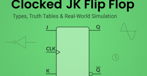
Clocked JK Flip Flop: Complete Guide with Circuit, Truth Table, and Working In the world of flip-flops, the Clocked JK Flip Flop stands out with its outstanding features, such as all usable input states and the ability to be modified to imitate other flip-flops like SR, T, and D. This makes the JK Flip Flop a little better than the others. It's often called a universal flip-flop. The JK flip-flop's main… |
|
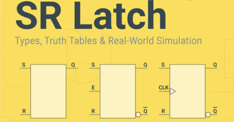
Understanding SR Latches: Complete Guide to Set-Reset Latch, Gated & Clocked Versions An SR latch is a basic memory element in digital electronics that stores binary data using Set and Reset inputs. This tutorial covers the SR latch truth table, the circuit diagram, and the working principle of basic, gated, and clocked SR latch variants. Initially, after the introduction of transistors, engineers constructed simple latch circuits using transistors. After several… |

|
Flip-Flop in Digital Electronics: Types, Truth Table, Logic Circuit and Practical Demonstration A flip-flop in digital electronics is formally defined as "A bistable device with synchronous inputs that changes state only at specified transitions of a clock signal" (IEEE Standard 91/1984) In general, flip-flops are fundamental components in digital electronics, capable of functioning as 1-bit memory storage devices. Unlike… |

|
Full Adder Circuit Diagram and its Construction In previous tutorial of half adder circuit construction, we had seen how computer uses single bit binary numbers 0 and 1 for addition and create SUM and Carry out. Today we will learn about the construction of Full-Adder Circuit. Here is a brief idea about Binary adders. Mainly there are two types of Adder: Half… |

|
How to Build a NAND Gate with Transistors? In the realm of digital electronics and logic circuits, the NAND gates stands as a fundamental cornerstone that wields immense power in information processing. NAND, short for Negated AND, is a logical operation that produces an output of low only when all of its inputs are high. In this article, we will… |

|
How to Build an XOR Gate with Transistors? In the vast world of digital electronics and logic circuits, The XOR gate stands as a fundamental building block that plays a crucial role in information processing. XOR, short for Exclusive OR. Is a logical operation that produces an output of high when the number of high inputs is odd, and low when the number of low inputs are even.… |

|
Standard Logic Devices in Ultra-Compact DHXQFN Packages Nexperia has developed small and low profile 14, 16, 20, and 24 pin DHXQFN packages to provide a small footprint in standard logic devices. Measuring just 2 mm x 2 mm (14 pin), 2 mm x 2.4 mm (16 pin), 2 mm x 3.2 mm (20 pin), and 2 mm x 4 mm (24 pin), the 0.4 mm pitch, 0.45 mm height, these DHXQFN packages help in saving space on PCB. The 16 pin… |

|
Implementation of Basic Logic Gates using VHDL in ModelSim Logic gates are the essential building blocks of digital circuits. These basic logic gates are used in Embedded Systems, Microcontrollers, Microprocessors, etc. Let us learn how to design the logic gates using VHDL in ModelSim. This tutorial is all about designing the basic logic gates using different VHDL modeling and their… |
|
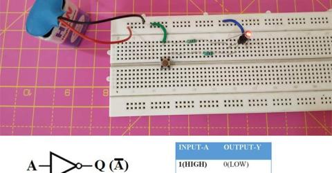
Designing NOT Gate using Transistors An Integrated Circuit or IC is a combination of many small circuits in a small package that together performs a common task. For example, an Operational Amplifier or 555 Timer IC is built by a combination of many Transistors, Flip-Flops, Logic Gates and other combinational digital circuits. Similarly, a Flip-Flop can be built by using a… |

|
Designing OR Gate using Transistor As many of us know an Integrated Circuit or IC is a combination of many small circuits in a small package which together performs a task. Like an Operational Amplifier or 555 Timer IC is built by a combination of many Transistors, Flip-Flops, Logic Gates and other combinational digital circuits. Similarly a Flip-Flop can be built by using a combination of Logic Gates and the… |

|
Designing an AND Gate using Transistors As many of us know, an Integrated Circuit or IC is a combination of many small circuits in a small package which together perform a common task. An Operational Amplifier or 555 Timer IC is built by a combination of many Transistors, Flip-Flops, Logic Gates and other combinational digital circuits. Similarly, a Flip-Flop can be built by using a combination of Logic Gates and… |
|
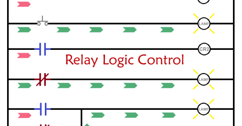
Introduction to Relay Logic Control - Symbols, Working and Examples Relay logic control systems are truly a foundation of industrial automation, and electromagnetic relays are necessary to perform switching actions in these conversion systems. The relay logic circuits also utilise relays along with switches, motors, timers, actuators, and contactors to form ON/OFF control systems effectively. Though relay logic control proves to be effective… |