In the vast world of digital electronics and logic circuits, The XOR gate stands as a fundamental building block that plays a crucial role in information processing. XOR, short for Exclusive OR. Is a logical operation that produces an output of high when the number of high inputs is odd, and low when the number of low inputs are even. This unique characteristic makes the XOR gate an essential component in various applications, ranging from simple binary arithmetic to complex data encryption algorithms.
In this article, we will explore the inner working of the XOR gate, including its truth table, logical symbol representation, circuit diagram, and practical construction using transistors.
Previously, we have built many electronic circuits to perform logic gates like XOR Gate, NAND Gate, NOT Gate, NOR Gate, AND Gate, OR Gate, XNOR Gate.
What is an XOR Logic Gate?
The XOR gate is also called the exclusive OR gate. An electronic XOR gate performs the digital logic XOR function. This function is generally similar to the standard OR function with one critical difference. For both OR and XOR, the output is high when either of the two inputs are high, and when both inputs are low, the output is low.
However, when both inputs are set to a high state, the standard OR circuit will produce a high output signal, whereas the XOR circuit will generate a low output signal. This fundamental behavior is the reason behind it is called exclusive OR gate. In the simplest design of XOR gate only 5 transistors are needed.
XOR Gate Symbol

Truth table of XOR gate
|
Inputs |
Output |
|
|
A |
B |
Y |
|
0 |
0 |
0 |
|
0 |
1 |
1 |
|
1 |
0 |
1 |
|
1 |
1 |
0 |
Boolean expression for this gate is
Y = (A ⊕ B)
Output
(A ⊕ B) = A.B + A.B
The truth table above shows clearly demonstrates that the output of an Exclusive-OR gate will only goes “HIGH” when both of its two input terminals are at different logic levels with respect to each other. If these two inputs, A and B are both at logic level “1” or both at logic level “0” the output is a “0”.
Logic Diagram of XOR Gate

As can be seen in the logic diagram above, the Ex-OR gate is built by combining three different types logic gates, the OR gate, the NAND gate and the AND gate to produce the desired result.
Components Needed for building XOR gate
So with just the few components, we can construct a XOR gate circuit.
- 2N2222 (NPN) transistors x5
- 10kΩ resistors x3
- 220Ω resistors x3
- Push buttons x2
- Breadboard x1
- 9V Battery x1
- LEDs and Connecting wires
Circuit Diagram of XOR Gate using Transistors
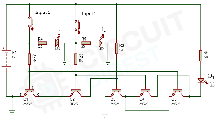
The circuit diagram below illustrates the XOR gate using 5 NPN transistors. Here, I1 and I2 represent the two inputs, and O1 signifies the output.
The picture shows a simple XOR gate circuit that uses 5 transistors. In the layout inputs A and B are both connected to 9V supply. Different color connecting wires help to see the connections. If there is any ambiguity in the placement of wires the circuit diagram can be referenced.
The gate design is a NAND gate on the left two transistors, a switch for the middle transistors, and an OR gate for the last two transistors.

Upon examining the configuration shown in the photo, it becomes evident that the current generated by the far-right resistor is unable to reach the ground on the lest, resulting in the LED remaining off. The reason behind this lies in the fact that all the current generated by the first resistor on the left is directed towards the first ground. Consequently, the switch remains in the off position due to insufficient voltage entering the base of the third transistor.
In the event that one input is activated, the current gains ability to flow from the far-right transistor to the second ground. Finally, when both inputs are deactivated, the output remains off since the current fails to enter the base of the OR gate transistors. this configuration prevents the current from traveling from the far-right resistor to the second ground.
Applications
From the depth of cryptography to the realm of error detection, the XOR gate proves to be an indispensable ally. It possesses the power to perform bitwise operation, enabling binary addition and subtraction, ensuring data integrity, and even generating parity checks. This gate’s versatility and elegance have solidified its role in countless digital system, paving the way for technological advancements that shape our modern world.


