
flip flop
|
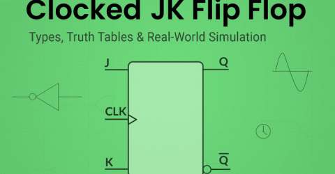
Clocked JK Flip Flop: Complete Guide with Circuit, Truth Table, and Working In the world of flip-flops, the Clocked JK Flip Flop stands out with its outstanding features, such as all usable input states and the ability to be modified to imitate other flip-flops like SR, T, and D. This makes the JK Flip Flop a little better than the others. It's often called a universal flip-flop. The JK flip-flop's main… |
|
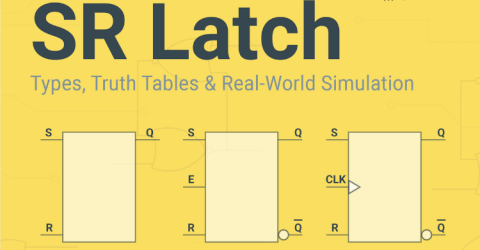
Understanding SR Latches: Complete Guide to Set-Reset Latch, Gated & Clocked Versions An SR latch is a basic memory element in digital electronics that stores binary data using Set and Reset inputs. This tutorial covers the SR latch truth table, the circuit diagram, and the working principle of basic, gated, and clocked SR latch variants. Initially, after the introduction of transistors, engineers constructed simple latch circuits using transistors. After several… |
|
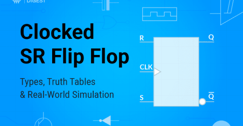
Clocked SR Flip Flop: Complete Guide with Circuit, Truth Table, and Working The Clocked SR flip flop is one of the most fundamental sequential logic circuits in digital electronics. Unlike basic SR latches, a clocked SR flip flop circuit uses a clock signal to control when state changes occur, making it essential for synchronous digital systems. This comprehensive guide covers the clocked SR flip flop truth table, circuit diagrams using both… |

|
Flip-Flop in Digital Electronics: Types, Truth Table, Logic Circuit and Practical Demonstration A flip-flop in digital electronics is formally defined as "A bistable device with synchronous inputs that changes state only at specified transitions of a clock signal" (IEEE Standard 91/1984) In general, flip-flops are fundamental components in digital electronics, capable of functioning as 1-bit memory storage devices. Unlike… |

|
T Flip-Flop: Circuit, Truth Table and Working The term digital in electronics represents the data generation, processing or storing in the form of two states. The two states can be represented as HIGH or LOW, positive or non-positive, set or reset which is ultimately binary. The high is 1 and low is 0 and hence the digital technology is expressed as series of 0’s and 1’s. An example is 011010 in which each term… |

|
What is Switch Bouncing and How to prevent it using Debounce Circuit Table of Contents What is Switch Bouncing and Debouncing? What is Software Debouncing? Switch Bouncing Circuit Diagram 1. Hardware Debouncing └ Components Required └ Debounce Circuit Diagram └ Working of the Hardware Debounce Circuit 2. RC Debounce Circuit 3. Debouncing Circuit for Push Button Using Specialised ICs Debouncing Methods… |
|
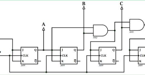
Synchronous CounterWhat is a Counter?
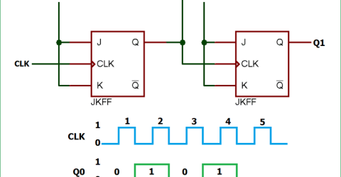
A counter is a device which can count any particular event on the basis of how many times the particular event(s) is occurred. In a digital logic system or computers, this counter can count and store the number of time any particular event or process have occurred, depending on a clock signal. Most common type of counter is sequential digital logic circuit… |
|
Asynchronous Counter An asynchronous counter (or ripple counter) is a sequential digital circuit in which the outputs of flip-flops are connected in series, so that the output of one flip-flop serves as the clock input to the next stage. Not all flip-flops may change state at the same time as synchronous counters, so asynchronous counters are easier to design but may experience propagation delays. Table of… |

|
Different Types of Shift Registers and its Applications with Examples What is Shift Register:
Shift Registers are sequential logic circuits, capable of storage and transfer of data. They are made up of Flip Flops which are connected in such a way that the output of one flip flop could serve as the input of the other flip-flop, depending on the type of shift registers being created. … |

|
JK Flip-Flop: Circuit, Truth Table and Working The term digital in electronics represents the data generation, processing or storing in the form of two states. The two states can be represented as HIGH or LOW, positive or non-positive, set or reset which is ultimately binary. The high is 1 and low is 0 and hence the digital technology is expressed as series of 0’s and 1’s. An example is 011010 in which each term… |

|
D Type Flip-Flop: Circuit, Truth Table and Working The term digital in electronics represents the data generation, processing or storing in the form of two states. The two states can be represented as HIGH or LOW, positive or non-positive, set or reset which is ultimately binary. The high is 1 and low is 0 and hence the digital technology is expressed as series of 0’s and 1’s. An example is 011010 in which each term… |
|
SR Flip-Flop with NAND Gates: Circuit, Truth Table and Working The SR flip flop using NAND gate truth table is a basic sequential logic circuit that holds one bit of digital information. This extensive guide goes over the general SR flip flop circuit diagram with explanation, a discussion of the truth table, and its implementation using IC SN74HC00N. If you want to become proficient in digital electronics and sequential circuit design, it's important to… |