

What is a Counter?
A counter is a device which can count any particular event on the basis of how many times the particular event(s) is occurred. In a digital logic system or computers, this counter can count and store the number of time any particular event or process have occurred, depending on a clock signal. Most common type of counter is sequential digital logic circuit with a single clock input and multiple outputs. The outputs represent binary or binary coded decimal numbers. Each clock pulse either increase the number or decrease the number.
Synchronous Counter
Synchrounous generally refers to something which is cordinated with others based on time. Synchronous signals occur at same clock rate and all the clocks follow the same reference clock.
In previous tutorial of Asynchronous Counter, we have seen that the output of that counter is directly connected to the input of next subsequent counter and making a chain system, and due to this chain system propagation delay appears during counting stage and create counting delays. In synchronous counter, the clock input across all the flip-flops use the same source and create the same clock signal at the same time. So, a counter which is using the same clock signal from the same source at the same time is called Synchronous counter.
Synchronous Up Counter
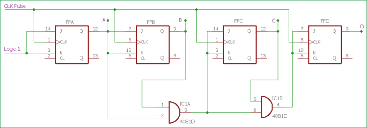
In the above image, the basic Synchronous counter design is shown which is Synchronous up counter. A 4-bit Synchronous up counter start to count from 0 (0000 in binary) and increment or count upwards to 15 (1111 in binary) and then start new counting cycle by getting reset. Its operating frequency is much higher than the same range Asynchronous counter. Also, there is no propagation delay in the synchronous counter just because all flip-flops or counter stage is in parallel clock source and the clock triggers all counters at the same time.
The external clock is directly provided to all J-K Flip-flops at the same time in a parallel way. If we see the circuit, the first flip-flop, FFA which is the least significant bit in this 4-bit synchronous counter, is connected to a Logic 1 external input via J and K pin. Due to this connection, HIGH logic across the Logic 1 signal, change the state of first flip-flop on every clock pulse.
Next stage, the second flip-flop FFB, input pin of J and K is connected across the output of the first Flip-flop. For the case of FFC and FFD, two separate AND gate provide the necessary logic across them. Those AND gates create logic using the input and output from the previous stage flip-flops.
We can create the same counting sequence used in the Asynchronous counter by making a situation where each flip-flops change its state depending on whether or not all preceding flip-flops output is HIGH in logic. But in this scenario, there will be no ripple effect just because all flip-flops are clocked at the same time.
Synchronous Down Counter
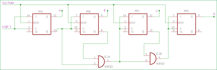
Slight changes in AND section, and using the inverted output from J-K flip-flop, we can create Synchronous Down Counter. A 4-bit Synchronous down counter start to count from 15 (1111 in binary) and decrement or count downwards to 0 or 0000 and after that it will start a new counting cycle by getting reset. In synchronous down counter, the AND Gate input is changed. First Flip-flop FFA input is same as we used in previous Synchronous up counter. Instead of directly feeding the output of the first flip-flop to the next subsequent flip-flop, we are using inverted output pin which is used to give J and K input across next flip-flop FFB and also used as input pin across the AND gate. Same as like the previous circuit, two AND gates are providing necessary logic to the next two Flip-flops FFC and FFD.
Synchronous Counter Timing Diagram

In the above image, clock input across flip-flops and the output timing diagram is shown. On each clock pulse, Synchronous counter counts sequentially. The counting output across four output pin is incremental from 0 to 15, in binary 0000 to 1111 for 4-bit Synchronous up counter. After the 15 or 1111, the counter reset to 0 or 0000 and count once again with a new counting cycle.
For Synchronous down counter where the inverted output is connected across the AND gate, exactly opposite counting step happens. The counter starts to count from 15 or 1111 to 0 or 0000 and then get restarted to start a new counting cycle and again start from 15 or 0000.
4 bit-Synchronous Decade Counter
Same as like Asynchronous counter, a Decade counter or BCD counter which can count 0 to can be made by cascading flip-flops. Same as like Asynchronous counter, it will also have “divide by n” feature with modulo or MOD number. We need to increase the MOD count of the Synchronous counter (can be in Up or Down configuration).
Here is the 4-bit Synchronous Decade counter circuit is shown-

Above circuit is made using Synchronous binary counter, which produces count sequence from 0 to 9. Additional logics are implemented for desired state sequence and to convert this binary counter to decade counter (base 10 numbers, Decimal). When the output reaches count 9 or 1001, the counter will reset to 0000 and again counts up to 1001.
In the above circuit, AND gates will detect the counting sequence reaches 9 or 1001 and change the state of a third flip-flop from the left, FFC to change its state on the next clock pulse. The counter then resets to 000 and again starts to count until 1001 is reached.
MOD-12 can be made from the above circuit if we change the position of AND gates and it will count 12 states from 0 (0000 in binary) to 11 (1011 in binary) and then reset to 0.
Trigger Pulse related information
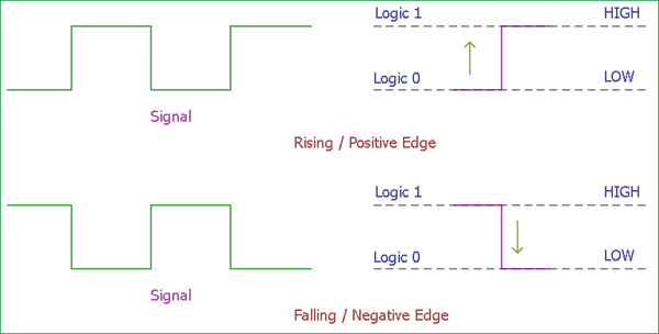
There are two type of edge triggered flip-flops available, Positive edge or Negative edge.
Positive Edge or Rising Edge flip-flops count one single step when the clock input changes its state from Logic 0 to Logic 1, in other term Logic Low to Logic High.
On the other hand, Negative Edge or falling Edge flip-flops count one single step when the clock input changes its state from Logic 1 to Logic 0, in other term Logic High to Logic Low.
Ripple counters use falling edge or negative edge triggered clock pluses to change state. There is a reason behind it. It will make easier opportunities to cascade counters together as the Most Significant bit of one counter could drive the clock input of next counter.
Synchronous counter offer carry out and carry in pin for counter linking related application. Due to this, there is no propagation delay inside the circuitry.
Advantages and Disadvantage of Synchronous Counter
Now we are familiar with Synchronous counter and what are the difference between the Asynchronous counter and Synchronous counter. Synchronous counter eliminates lots of limitations which arrive in Asynchronous counter.
The advantages of the Synchronous counter is as follows-
- It’s easier to design than the Asynchronous counter.
- It acts simultaneously.
- No propagation delay associated with it.
- Count sequence is controlled using logic gates, error chances are lower.
- Faster operation than the Asynchronous counter.
Although there are many advantages, one major disadvantage of working with Synchronous counter is that it requires a lot of extra logic to perform.
Use of Synchronous Counter
Few applications where Synchronous counters are used-
- Machine Motion control
- Motor RPM counter
- Rotary Shaft Encoders
- Digital clock or pulse generators.
- Digital Watch and Alarm systems.
