

An asynchronous counter (or ripple counter) is a sequential digital circuit in which the outputs of flip-flops are connected in series, so that the output of one flip-flop serves as the clock input to the next stage. Not all flip-flops may change state at the same time as synchronous counters, so asynchronous counters are easier to design but may experience propagation delays.
Table of Contents
- What is a Counter in Digital Electronics?
- └ Key Characteristics
- What Does Asynchronous Mean in Digital Circuits?
- Counter Fundamentals and Operation
- How Asynchronous Counters Work
- Asynchronous Counter vs Synchronous Counter
- 4-Bit Circuit Diagram
- └ Asynchronous Decade Counter (BCD Counter) Design
- Asynchronous Counter Truth Table
- Timing Diagram Analysis
- Advantages and Disadvantages
What is a Counter in Digital Electronics?
A counter is a device which can count any particular event based on how many times the particular event occurs. In a digital logic system or computers, this counter can count and store the number of times any particular event or process has occurred, depending on a clock signal. The most common type of counter is a sequential digital logic circuit with a single clock input and multiple outputs. The outputs represent binary or binary-coded decimal numbers. Each clock pulse either increases the number or decreases the number. Modern counters can be classified into two main categories: asynchronous counters (ripple counters) and synchronous counters.
Key Characteristics of Digital Counters
Sequential Operation: Counters maintain state memory through flip-flops
Clock-Driven: State changes occur based on clock signal transitions
Binary Output: Display count values in binary, BCD, or other coded formats
Modulo Operation: Count capacity determined by number of flip-flops (MOD-2n)
Directional Counting: Support up-counting, down-counting, or bi-directional operation
What Does Asynchronous Mean in Digital Circuits?
In digital systems, asynchronous refers to operations that occur without synchronised timing across all components. Asynchronous stands for the absence of synchronisation. Something that does not exist or occurs at the same time. In computing or telecommunication stream, Asynchronous stands for controlling the operation timing by sending a pulse only when the previous operation is completed, rather than sending it in regular intervals.
In the context of asynchronous counters in digital electronics, this means each flip-flop is clocked by the output of the previous stage rather than a common clock source. This creates a "ripple" effect where state changes cascade through the counter stages, giving rise to the alternate name "asynchronous ripple counter."
Asynchronous Counter Fundamentals and Operation
Now we understand what a counter is and what is the meaning of the word Asynchronous means. An Asynchronous counter can count using an Asynchronous clock input. An asynchronous counter is a sequential digital circuit. Counters can be easily made using flip-flops. As the count depends on the clock signal, in the case of an Asynchronous counter, changing state bits are provided as the clock signal to the subsequent flip-flops. Those Flip-flops are serially connected, and the clock pulse ripples through the counter. Due to the ripple clock pulse, it’s often called a ripple counter. An Asynchronous counter can count 2n - 1 possible counting states. This configuration creates an asynchronous up counter or down counter, depending on which output (Q or Q̄) is used as the clock source.
How Asynchronous Counters Work:
As there is a maximum output number for Asynchronous counters like MOD-16 with a resolution of 4-bit, there are also possibilities to use a basic Asynchronous counter in a configuration where the counting state will be less than their maximum output number. Modulo or MOD counters are one of those types of counters. The configuration is made in such a way that the counter will reset itself to zero at a pre-configured value and has truncated sequences.
So, if a counter with the specific number of resolutions (n-bit Resolution) counts up to is called a full sequence counter, and on the other hand, if it counts less than the maximum number, it is called a truncated counter.
To get the advantage of the asynchronous inputs in the flip-flop, an Asynchronous Truncated counter can be used with combinational logic.
A modulo 16 asynchronous counter can be modified using additional logic gates and can be used in a way that the output will give a decade (divided by 10) counter output, which is useful in counting standard decimal numbers or in arithmetic circuits. This type of counter is called a Decade counter.
Decade Counters requires resetting to zero when the output reaches a decimal value of 10.
If we count 0-9 (10 steps), the binary number will be –
| Number Count | Binary Number | Decimal Value |
| 0 | 0000 | 0 |
| 1 | 0001 | 1 |
| 2 | 0010 | 2 |
| 3 | 0011 | 3 |
| 4 | 0100 | 4 |
| 5 | 0101 | 5 |
| 6 | 0110 | 6 |
| 7 | 0111 | 7 |
| 8 | 1000 | 8 |
| 9 | 1001 | 9 |
So, when the output reaches 1001 (BCD = 9), the counter needs to be reset. To reset the counter, we need to feed this condition back to the reset input. A counter which counts 0000 (BCD = 0) to 1001 (BCD = 9) is referred to as a BCD or Binary-coded Decimal counter.
Asynchronous Counter vs Synchronous Counter: Key Differences
| Feature | Asynchronous Counter | Synchronous Counter |
| Clock Signal | Different clock for each flip-flop (ripple through) | Common clock for all flip-flops |
| Speed | Slower due to cumulative propagation delays | Faster - all flip-flops change simultaneously |
| Circuit Complexity | Simple design, fewer logic gates | Complex design, requires additional logic |
| Power Consumption | Lower power consumption | Higher power consumption |
| Propagation Delay | Cumulative delay (n × tpd) | Single flip-flop delay (tpd) |
| Maximum Frequency | Limited by total propagation delay | Higher maximum operating frequency |
| Glitches | Susceptible to decoding glitches | Glitch-free operation |
| Applications | Frequency dividers, low-speed counting | High-speed applications, processor timing |
4-Bit Asynchronous Counter Design and Circuit Diagram
A 4-bit asynchronous counter is one of the most commonly used configurations in digital electronics.

Asynchronous Decade Counter (BCD Counter) Design
In the above image, a basic Asynchronous counter is used as a decade counter configuration using 4 JK Flip-Flops and one NAND gate 74LS10D. The Asynchronous counter counts upwards on each clock pulse, starting from 0000 (BCD = 0) to 1001 (BCD = 9). Each JK flip-flop output provides a binary digit, and the binary out is fed into the next subsequent flip-flop as a clock input. In the final output 1001, which is 9 in decimal, the output D, which is the Most Significant bit and the Output A, which is the Least Significant bit, both are in Logic 1. These two outputs are connected across the 74LS10D’s input. When the next clock pulse is received, the output of 74LS10D reverts the state from Logic High or 1 to Logic Low or 0.
In such a situation, when the 74LS10D changes the output, the 74LS73 J-K Flip-flops will get reset as the output of the NAND gate is connected across the 74LS73 CLEAR input. When the flip-flops reset, the output from D to A all became 0000, and the output of the NAND gate reset back to Logic 1. With such a configuration, the upper circuit shown in the image became a Modulo-10 or a decade counter.
Asynchronous Counter Truth Table: Decade Counter States
The Truth table of the Decade counter is shown in the next table-
| Clock Pulse | Decimal Value | Output - D | Output – C | Output – B | Output - A |
| 1 | 0 | 0 | 0 | 0 | 0 |
| 2 | 1 | 0 | 0 | 0 | 1 |
| 3 | 2 | 0 | 0 | 1 | 0 |
| 4 | 3 | 0 | 0 | 1 | 1 |
| 5 | 4 | 0 | 1 | 0 | 0 |
| 6 | 5 | 0 | 1 | 0 | 1 |
| 7 | 6 | 0 | 1 | 1 | 0 |
| 8 | 7 | 0 | 1 | 1 | 1 |
| 9 | 8 | 1 | 0 | 0 | 0 |
| 10 | 9 | 1 | 0 | 0 | 1 |
| 11 | 0 | 0 | 0 | 0 | 0 |
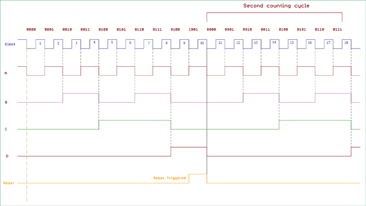
Timing Diagram Analysis
The asynchronous counter diagram below shows a decade counter implementation using four 74LS73 JK flip-flops and a 74LS10D NAND gate. The image below shows the timing diagram and the 4 outputs' status on the clock signal. The reset pulse is also shown in the diagram.
Asynchronous Counter Design: Practical Examples and Calculations
Designing custom asynchronous counters requires understanding modulus calculations and feedback logic implementation. We can modify the counting cycle for the Asynchronous counter using the method which is used in truncating counter output. For other counting cycles, we can change the input connection across the NAND gate or add other logic gate configurations.
As we discussed before, the maximum modulus that can be implemented with n numbers of flip-flops is 2n. For this, if we want to design a truncated asynchronous counter, we should find out the lowest power of two, which is either greater than or equal to our desired modulus.
For example, if we want to count 0 to 56 or mod – 57 and repeat from 0, the highest number of flip-flops required is n = 6, which will give a maximum modulus of 64. If we choose fewer numbers of flip-flops, the modulus will not be sufficient to count the numbers from 0 to 56. If we choose n = 5, the maximum MOD will be = 32, which is insufficient for the count.
We can cascade two or more 4-bit ripple counters and configure each individual as “divided by 16” or “divided by 8” formations to get a MOD-128 or more specified counter.
In the 74LS segment, the 7493 IC could be configured in such a way that if we configure 7493 as a “divided by 16” counter and cascade another 7493 chip as a “divided by 8” counter, we will get a “divide by 128” frequency divider.
Other ICs like 74LS90 offer programmable ripple counter or divider that can be configured as a divide by 2, divide by 3 or divide by 5 or other combinations as well.
On the other hand, 74LS390 is another flexible choice which can be used for a large division by a number from 2 to 50,100 and other combinations as well.
Asynchronous Counter Applications: Frequency Dividers
One of the best uses of the asynchronous counter is to use it as a frequency divider. We can reduce the high clock frequency down to a usable, stable value much lower than the actual high-frequency clock. This is very useful in case of digital electronics, timing-related applications, digital clocks, and interrupt source generators.
Suppose we are using a classic NE555 timer IC, which is a Monostable/Astable Multivibrator, running at 260 kilohertz, and the stability is +/- 2 %. We can easily add a “Divided by 2” 18-bit ripple counter and get a 1 Hz stable output, which can be used for generating 1-second of delay or 1-second of the pulse, which is useful for digital clocks.
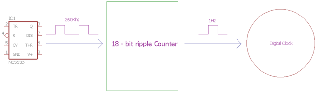
This is a simple circuit to produce a stable frequency or timing from an unstable source by dividing the frequency using a ripple counter. More precise crystal oscillators can produce precise high-frequency signals, other than the signal generators.
Advantages and Disadvantages of an Asynchronous Counter
Asynchronous counters can be easily built using Type D flip-flops. They can be implemented using a “divide by n” counter circuit, which offers much more flexibility for larger counting range-related applications, and the truncated counter can produce any modulus number count.
But, despite those features, Asynchronous counter offers some limitations and disadvantages.
While using the Asynchronous counter, an additional resynchronizing output flip-flop is required for resynchronizing the flip-flops. Also, for the truncated sequence count, when it is not equal to, extra feedback logic is needed.
When counting a large number of bits, due to the chain system, the propagation delay by successive stages becomes too large, which is very difficult to get rid of. In such a situation, Synchronous counters are faster and reliable. There are also counting errors in the Asynchronous Counter when high clock frequencies are applied across it.
Frequently Asked Questions (FAQs) About Asynchronous Counters
⇥ 1. Why is an asynchronous counter called a ripple counter?
This is called a ripple counter because the clock pulses "ripple" through the flip-flops in sequence. That is, the output transition of one flip-flop triggers the next, and so forth, as a kind of wave propagates the state change through the stages of the counter, much like ripples spread on water.
⇥ 2. How do you design a MOD-10 decade counter using asynchronous logic?
A MOD-10 decade counter requires four JK flip-flops and a NAND gate. Connect flip-flops in cascade for a 4-bit counter. Feed outputs Q3 and Q0 to the NAND gate, connecting its output to all CLEAR pins. When the count reaches 1001 (decimal 9), the next pulse triggers a reset to 0000, creating a decade counter.
⇥ 3. What causes the propagation delay occurring in ripple or asynchronous counters?
Propagation delay occurs naturally with all flip-flops having a defined switching time of about 5-20 nanoseconds. If one flip-flop has a delay, the delay quickly builds when signals ripple from flip-flop to flip-flop. The propagation delay of a n bit binary counter can be simply stated as n x the delay of one flip-flop. This propagation delay results in a maximum frequency of operation when compared to synchronous counters.
⇥ 4. Can asynchronous counters count down as well as up?
Yes, asynchronous counters can count down by connecting each flip-flop's Q̄ (inverted) output to the next stage's clock input instead of Q output. It will reverse the counting sequence. Down-counting can be achieved while keeping the Q output connected between stages by using negative-edge-triggered flip-flops.
⇥ 5. What are truncated counters, and how would you implement them?
Truncated counters count fewer states than their maximum possible states, or 2n. A truncated counter is implemented with feedback logic that first detects the wanted terminal count, then resets the flip-flops. For example, a 4-bit counter (MOD-16) would be a MOD-10 counter with the addition of NAND gate feedback.
⇥ 6. Besides being used as a general counter, what are some common applications of asynchronous counters in electronic circuits?
Asynchronous counters function as frequency dividers, digital clocks, event counters, timer circuits, and baud rate generators. They are used frequently as a prescaler device in measurement devices, pulse-generating circuits, and low-power-consuming counting devices where speed is not a major design criterion. Propagation delay still exists for asynchronous counters, but is often ignored because of the general applicability of these devices. They also must be somewhat cost-sensitive, which makes them stupendously simple if they are intended for use in low-power devices in educational and other noncritical applications.
⇥ 7. How do you get decoding glitches that arise in asynchronous counters, and how do you prevent them?
Decoding glitches happen because flip-flops do not change at the same time and will briefly exhibit an intermediate state during the ripple. You can prevent ordering glitches by adding latches to the output that will clock out after the settling time, or using a strobe decoder, which will activate during the transitions or by laminating audio-glitch-free decoding circuits or even using some variation of the synchronous counter design method, which is inherently glitch-free.
Exploring Asynchronous Communication: Concepts, Circuits, and Serial Interfaces
Learn the fundamentals of asynchronous communication, from SR latch operation to RS-485 serial interfacing, and understand how data is transferred without a common clock signal.

Serial Communication Protocols
In an asynchronous Serial Interface, the absence of an external Clock Source makes it rely on several parameters, such as Data Flow Control, Error Control, Baud Rate Control, Transmission Control, and Reception Control.

RS-485 Serial Communication between Raspberry Pi and Arduino Uno
RS-485 is an asynchronous serial communication protocol which does not require a clock. It uses a technique called differential signal to transfer binary data from one device to another.

Understanding SR Latches: Complete Guide to Set-Reset Latch, Gated & Clocked Versions
On the other hand, compared to flip-flops, latches are asynchronous sequential circuits and do not operate with the help of a clock signal.
