Human Following Robot Using Arduino and Ultrasonic Sensor
Working of Human Following Robot Using Arduino
In recent years, robotics has witnessed significant advancements, enabling the creation of intelligent machines that can interact with the environment. One exciting application of robotics is the development of human-following robots. These robots can track and follow a person autonomously, making them useful in various scenarios like assistance in crowded areas, navigation support, or even as companions. In this article, we will explore in detail how to build a human following robot using Arduino and three ultrasonic sensors, complete with circuit diagrams and working code. Also, check all the Arduino-based Robotics projects by following the link.
The working of a human following robot using Arduino code and three ultrasonic sensors is an interesting project. What makes this project particularly interesting is the use of not just one, but three ultrasonic sensors. This adds a new dimension to the experience, as we typically see humans following a robot built with one ultrasonic, two IR, and one servo motor. This servo motor has no role in the operation and also adds unnecessary complications. So I removed this servo and the IR sensors and used 3 ultrasonic sensors. With ultrasonic sensors, you can measure distance and use that information to navigate and follow a human target. Here’s a general outline of the steps involved in creating such a robot.
Table of Contents
- Working of Human Following Robot Using Arduino
- Components Needed for Human Following Robot Using Arduino
- Human Following Robot Using Arduino Circuit Diagram
- Human Following Robot Using Arduino Code
- Important aspects of this Arduino-powered human-following robot project include:
- Technical Summary and GitHub Repository
- Frequently Asked Questions
- Conclusion
- Explore Practical Projects Similar To Robots Using Arduino
Components Needed for Human Following Robot Using Arduino
Arduino UNO board ×1
Ultrasonic sensor ×3
L298N motor driver ×1
Robot chassis
BO motors ×2
Wheels ×2
Li-ion battery 3.7V ×2
Battery holder ×1
Breadboard
Ultrasonic sensor holder ×3
Switch and jumper wires
Human Following Robot Using Arduino Circuit Diagram
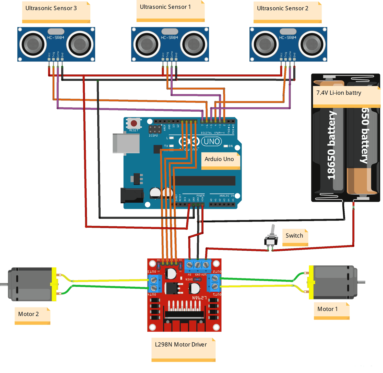
Here is the schematic diagram of a Human-following robot circuit.
This design incorporates three ultrasonic sensors, allowing distance measurements in three directions front, right, and left. These sensors are connected to the Arduino board through their respective digital pins. Additionally, the circuit includes two DC motors for movement, which are connected to an L298N motor driver module. The motor driver module is, in turn, connected to the Arduino board using its corresponding digital pins. To power the entire setup, two 3.7V li-ion cells are employed, which are connected to the motor driver module via a switch.
Overall, this circuit diagram showcases the essential components and connections necessary for the Human-following robot to operate effectively.

Circuit Connection:
Arduino and HC-SR04 Ultrasonic Sensor Module:

Connect the VCC pin of each ultrasonic sensor to the 5V pin on the Arduino board.
Connect the GND pin of each ultrasonic sensor to the GND pin on the Arduino board.
Connect the trigger pin (TRIG) of each ultrasonic sensor to separate digital pins (2,4, and 6) on the Arduino board.
Connect the echo pin (ECHO) of each ultrasonic to separate digital pins (3,5, and 7) on the Arduino board.
Arduino and Motor Driver Module:
Connect the digital output pins of the Arduino (digital pins 8, 9, 10, and 11) to the appropriate input pins (IN1, IN2, IN3, and IN4) on the motor driver module.
Connect the ENA and ENB pins of the motor driver module to the onboard High state pin with the help of a female header.
Connect the OUT1, OUT2, OUT3, and OUT4 pins of the motor driver module to the appropriate terminals of the motors.
Connect the VCC (+5V) and GND pins of the motor driver module to the appropriate power (Vin) and ground (GND) connections on the Arduino.
Power Supply:
Connect the positive terminal of the power supply to the +12V input of the motor driver module.
Connect the negative terminal of the power supply to the GND pin of the motor driver module.
Connect the GND pin of the Arduino to the GND pin of the motor driver module.
Human Following Robot Using Arduino Code
Here is a simple 3 Ultrasonic sensor-based Human following robot using Arduino Uno code that you can use for your project.

This code reads the distances from three ultrasonic sensors (‘frontDistance’, ‘leftDistance’, and ‘rightDistance’). It then compares these distances to determine the sensor with the smallest distance. If the smallest distance is below the threshold, it moves the car accordingly using the appropriate motor control function (‘moveForward()’, ‘turnLeft()’, ‘turnRight()’). If none of the distances are below the threshold, it stops the motor using ‘stop()’.
In this section, we define the pin connections for the ultrasonic sensors and motor control. The S1Trig, S2Trig, and S3Trig, variables represent the trigger pins of the three ultrasonic sensors, while S1Echo, S2Echo, and S3Echo, represent their respective echo pins.
The LEFT_MOTOR_PIN1, LEFT_MOTOR_PIN2, RIGHT_MOTOR_PIN1, and RIGHT_MOTOR_PIN2 variables define the pins for controlling the motors.
The MAX_DISTANCE and MIN_DISTANCE_BACK variables set the thresholds for obstacle detection.
// Ultrasonic sensor pins
#define S1Trig 2
#define S2Trig 4
#define S3Trig 6
#define S1Echo 3
#define S2Echo 5
#define S3Echo 7
// Motor control pins
#define LEFT_MOTOR_PIN1 8
#define LEFT_MOTOR_PIN2 9
#define RIGHT_MOTOR_PIN1 10
#define RIGHT_MOTOR_PIN2 11
// Distance thresholds for obstacle detection
#define MAX_DISTANCE 40
#define MIN_DISTANCE_BACK 5
Make sure to adjust the values of ‘MIN_DISTANCE_BACK’ and ‘MAX_DISTANCE’ according to your specific requirements and the characteristics of your robot.
The suitable values for ‘MIN_DISTANCE_BACK’ and ‘MAX_DISTANCE’ depend on the specific requirements and characteristics of your human-following robot. You will need to consider factors such as the speed of your robot, the response time of the sensors, and the desired safety margin
Here are some general guidelines to help you choose suitable values.
‘MIN_DISTANCE_BACK’ This value represents the distance at which the car should come to a stop when an obstacle or hand is detected directly in front. It should be set to a distance that allows the car to back safely without colliding with the obstacle or hand. A typical value could be around 5-10 cm.
‘MAX_DISTANCE’ This value represents the maximum distance at which the car considers the path ahead to be clear and can continue moving forward. It should be set to a distance that provides enough room for the car to move without colliding with any obstacles or hands. If your hand and obstacles are going out of this range, the robot should be stop. A typical value could be around 30-50 cm.
These values are just suggestions, and you may need to adjust them based on the specific characteristics of your robot and the environment in which it operates.
These lines set the motor speed limits. ‘MAX_SPEED’ denotes the upper limit for motor speed, while ‘MIN_SPEED’ is a lower value used for a slight left bias. The speed values are typically within the range of 0 to 255, and can be adjusted to suit our specific requirements.
// Maximum and minimum motor speeds
#define MAX_SPEED 150
#define MIN_SPEED 75
The ‘setup()’ function is called once at the start of the program. In the setup() function, we set the motor control pins (LEFT_MOTOR_PIN1, LEFT_MOTOR_PIN2, RIGHT_MOTOR_PIN1, RIGHT_MOTOR_PIN2) as output pins using ‘pinMode()’ . We also set the trigger pins (S1Trig, S2Trig, S3Trig) of the ultrasonic sensors as output pins and the echo pins (S1Echo, S2Echo, S3Echo) as input pins. Lastly, we initialize the serial communication at a baud rate of 9600 for debugging purposes.
void setup() {
  // Set motor control pins as outputs
  pinMode(LEFT_MOTOR_PIN1, OUTPUT);
  pinMode(LEFT_MOTOR_PIN2, OUTPUT);
  pinMode(RIGHT_MOTOR_PIN1, OUTPUT);
  pinMode(RIGHT_MOTOR_PIN2, OUTPUT);
  //Set the Trig pins as output pins
  pinMode(S1Trig, OUTPUT);
  pinMode(S2Trig, OUTPUT);
  pinMode(S3Trig, OUTPUT);
  //Set the Echo pins as input pins
  pinMode(S1Echo, INPUT);
  pinMode(S2Echo, INPUT);
  pinMode(S3Echo, INPUT);
  // Initialize the serial communication for debugging
  Serial.begin(9600);
}
This block of code consists of three functions (‘sensorOne()’, ‘sensorTwo()’, ‘sensorThree()’) responsible for measuring the distance using ultrasonic sensors.
The ‘sensorOne()’ function measures the distance using the first ultrasonic sensor. It's important to note that the conversion of the pulse duration to distance is based on the assumption that the speed of sound is approximately 343 meters per second. Dividing by 29 and halving the result provides an approximate conversion from microseconds to centimeters.
The ‘sensorTwo()’ and ‘sensorThree()’ functions work similarly, but for the second and third ultrasonic sensors, respectively.
// Function to measure the distance using an ultrasonic sensor
int sensorOne() {
  //pulse output
  digitalWrite(S1Trig, LOW);
  delayMicroseconds(2);
  digitalWrite(S1Trig, HIGH);
  delayMicroseconds(10);
  digitalWrite(S1Trig, LOW);
  long t = pulseIn(S1Echo, HIGH);//Get the pulse
  int cm = t / 29 / 2; //Convert time to the distance
  return cm; // Return the values from the sensor
}
//Get the sensor values
int sensorTwo() {
  //pulse output
  digitalWrite(S2Trig, LOW);
  delayMicroseconds(2);
  digitalWrite(S2Trig, HIGH);
  delayMicroseconds(10);
  digitalWrite(S2Trig, LOW);
  long t = pulseIn(S2Echo, HIGH);//Get the pulse
  int cm = t / 29 / 2; //Convert time to the distance
  return cm; // Return the values from the sensor
}
//Get the sensor values
int sensorThree() {
  //pulse output
  digitalWrite(S3Trig, LOW);
  delayMicroseconds(2);
  digitalWrite(S3Trig, HIGH);
  delayMicroseconds(10);
  digitalWrite(S3Trig, LOW);
  long t = pulseIn(S3Echo, HIGH);//Get the pulse
  int cm = t / 29 / 2; //Convert time to the distance
  return cm; // Return the values from the sensor
}
In this section, the ‘loop()’ function begins by calling the ‘sensorOne()’, ‘sensorTwo()’, and ‘sensorThree()’ functions to measure the distances from the ultrasonic sensors. The distances are then stored in the variables ‘frontDistance’, ‘leftDistance’, and ‘rightDistance’.
Next, the code utilizes the ‘Serial’ object to print the distance values to the serial monitor for debugging and monitoring purposes.
void loop() {
  int frontDistance = sensorOne();
  int leftDistance = sensorTwo();
  int rightDistance = sensorThree();
  Serial.print("Front: ");
  Serial.print(frontDistance);
  Serial.print(" cm, Left: ");
  Serial.print(leftDistance);
  Serial.print(" cm, Right: ");
  Serial.print(rightDistance);
  Serial.println(" cm");
In this section of code condition checks if the front distance is less than a threshold value ‘MIN_DISTANCE_BACK’ that indicates a very low distance. If this condition is true, it means that the front distance is very low, and the robot should move backward to avoid a collision. In this case, the ‘moveBackward()’ function is called.
if (frontDistance < MIN_DISTANCE_BACK) {
    moveBackward();
    Serial.println("backward");
If the previous condition is false, this condition is checked. if the front distance is less than the left distance, less than the right distance, and less than the ‘MAX_DISTANCE’ threshold. If this condition is true, it means that the front distance is the smallest among the three distances, and it is also below the maximum distance threshold. In this case, the ‘moveForward()’ function is called to make the car move forward.
else if (frontDistance < leftDistance && frontDistance < rightDistance && frontDistance < MAX_DISTANCE) {
    moveForward();
    Serial.println("forward");
If the previous condition is false, this condition is checked. It verifies if the left distance is less than the right distance and less than the ‘MAX_DISTANCE’ threshold. This condition indicates that the left distance is the smallest among the three distances, and it is also below the minimum distance threshold. Therefore, the ‘turnLeft()’ function is called to make the car turn left.
else if (leftDistance < rightDistance && leftDistance < MAX_DISTANCE) {
    turnLeft();
    Serial.println("left");
If neither of the previous conditions is met, this condition is checked. It ensures that the right distance is less than the ‘MAX_DISTANCE’ threshold. This condition suggests that the right distance is the smallest among the three distances, and it is below the minimum distance threshold. The ‘turnRight()’ function is called to make the car turn right.
else if (rightDistance < MAX_DISTANCE) {
    turnRight();
    Serial.println("right");
If none of the previous conditions are true, it means that none of the distances satisfy the conditions for movement. Therefore, the ‘stop()’ function is called to stop the car.
 else {
    stop();
    Serial.println("stop");
In summary, the code checks the distances from the three ultrasonic sensors and determines the direction in which the car should move based on the 3 ultrasonic sensors with the smallest distance.
Important aspects of this Arduino-powered human-following robot project include:
- Three-sensor setup for 360-degree human identification
- Distance measurement and decision-making in real-time
- Navigation that operates automatically without human assistance
- Avoiding collisions and maintaining a safe following distance
Technical Summary and GitHub Repository
Using three HC-SR04 ultrasonic sensors and an L298N motor driver for precise directional control, this Arduino project shows off the robot's ability to track itself. For simple replication and modification, the full source code, circuit schematics, and assembly guidelines are accessible in our GitHub repository. To download the Arduino code, view comprehensive wiring schematics, and participate in the open-source robotics community, visit our GitHub page.
Frequently Asked Questions
⇥ How does an Arduino-powered human-following robot operate?
Three ultrasonic sensors are used by the Arduino-powered human following robot to determine a person's distance and presence. After processing this data, the Arduino manages motors to follow the identified individual while keeping a safe distance.
⇥ Which motor driver is ideal for an Arduino human-following robot?
The most widely used motor driver for Arduino human-following robots is the L298N. Additionally, some builders use the L293D motor driver shield, which connects to the Arduino Uno directly. Both can supply enough current for small robot applications and manage 2-4 DC motors.
⇥ Is it possible to create a human-following robot without soldering?
Yes, you can use motor driver shields that connect straight to an Arduino, breadboards, and jumper wires to construct a human-following robot. For novices and prototyping, this method is ideal.
⇥ What uses do human-following robots have in the real world?
Shopping cart robots in malls, luggage-carrying robots in airports, security patrol robots, elderly care assistance robots, educational demonstration robots, and companion robots that behave like pets are a few examples of applications.
Conclusion
This human following robot using Arduino project and three ultrasonic sensors is an exciting and rewarding project that combines programming, electronics, and mechanics. With Arduino’s versatility and the availability of affordable components, creating your own human-following robot is within reach.
Human-following robots have a wide range of applications in various fields, such as retail stores, malls, and hotels, to provide personalized assistance to customers. Human-following robots can be employed in security and surveillance systems to track and monitor individuals in public spaces. They can be used in Entertainment and events, elderly care, guided tours, research and development, education and research, and personal robotics.
They are just a few examples of the applications of human-following robots. As technology advances and robotics continues to evolve, we can expect even more diverse and innovative applications in the future.
Explore Practical Projects Similar To Robots Using Arduino
Explore a range of hands-on robotics projects powered by Arduino, from line-following bots to obstacle-avoiding vehicles. These practical builds help you understand sensor integration, motor control, and real-world automation techniques. Ideal for beginners and hobbyists, these projects bring theory to life through interactive learning.
Simple Light Following Robot using Arduino UNO
Today, we are building a simple Arduino-based project: a light-following robot. This project is perfect for beginners, and we'll use LDR sensor modules to detect light and an MX1508 motor driver module for control. By building this simple light following robot you will learn the basics of robotics and how to use a microcontroller like Arduino to read sensor data and control motors.
Line Follower Robot using Arduino UNO: How to Build (Step-by-Step Guide)
This step-by-step guide will show you how to build a professional-grade line follower robot using Arduino UNO, with complete code explanations and troubleshooting tips. Perfect for beginners and intermediate makers alike, this project combines hardware interfacing, sensor calibration, and motor control fundamentals.

