
Looking to add motion control to your Arduino projects? Whether you're building a robot, conveyor system, remote-controlled car, or any other motorized project, controlling motor speed and direction is essential. The L298N Motor Driver Module is a powerful and cost-effective solution for driving DC motors and stepper motors with Arduino. This versatile dual H-Bridge motor driver makes it easy to control motor movement, offering features like forward and reverse rotation, speed control using PWM, and built-in protection mechanisms.
In this Arduino motor control tutorial, we’ll guide you through interfacing the L298N with Arduino, understanding its working principle, and writing code to run a DC motor forward and backward with variable speed control. Once you have learnt how to control a DC motor, you can check out our Arduino Projects and Robotics Projects to build many exciting projects using this module. Let’s get started!
Table of Contents
- L298N Motor Driver Module
- Features of L298N Motor Driver
- Specifications and Datasheet
- L298N Motor Driver Module Pinout
- Internal Schematics of L298N Motor Driver Module
- How to Use L298N Motor Driver Module
- Components Required
- Video Tutorial
- Circuit Diagram for Interfacing L298N Motor Driver with Arduino
- Arduino Code for L298N Motor Driver Module
- Working Demonstration
- GitHub Repo with Code and Circuit
- Frequently Asked Questions
- Projects using L298N Motor Driver
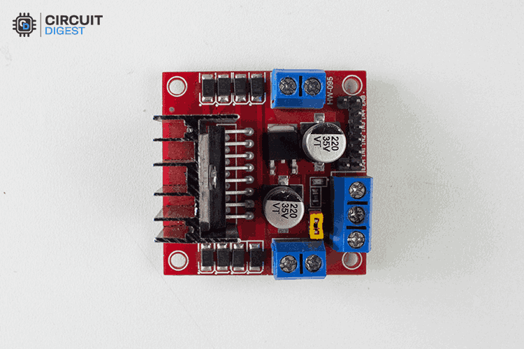
L298N Motor Driver Module
The L298N is a dual H-Bridge motor driver specifically designed to control the DC motors and stepper motors with high efficiency. It finds its application in various fields like Robotics, Automation, and Motorized projects due to its ability to handle higher voltage and current when compared to other compact motor drivers like MX1508 or the DRV8833.
Features of L298N Motor Driver
Let's jump on to learn about key features of the L298N Motor Driver, which plays a huge role in controlling heavy-load DC motors.
It is based on a Dual H-Bridge design for controlling two DC motors independently.
It supports both forward and reverse motor control with stop and brake functionality.
Operates at a wide voltage range from 5V to 35V.
It can handle up to 2A per motor continuously, with peak current handling capacity up to 3A.
It utilizes the Pulse width modulation via ENA and ENB pins to control the speed of the motor rotation.
Equipped with a Thermal Shutdown feature to prevent the circuit from getting damaged during high current operations.
We can utilize the built-in 78M05 5V Voltage regulator to power the logic circuit when only a 12V supply is given for driving the logic and driver circuit.
I hope now, you have some idea about L298N. Next, we are going to learn the in-depth specifications of this motor driver module.
Specifications and Datasheet
In the market, some cloned versions of the L298N Motor Driver module may use alternative equivalent ICs, so always check the specific IC used in your module before relying on the below specifications. The data provided below is based on the L298N driver IC. You can also check out the L298N motor Driver Module Datasheet if you need more information.
Next, we are going to look at the pinout details of the L298N Motor Driver Module, which is crucial to know for controlling the motor via Arduino.
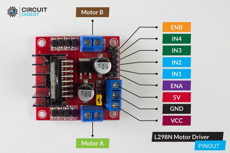
L298N Motor Driver Module Pinout
The L298N module pinout is simple and easy to understand. It follows a structure similar to most drivers but what makes it different is, that it has a separate voltage input for the motor and the logic circuit, which allows better power management
Here is one thing you want to consider, i.e. if you are using a DC motor with a voltage rating (<=12V), you don’t need to provide a separate power supply for the Logic Circuit via 5V Pin. By connecting the jumper as shown in the image below, You can enable the 5V regulator present on the driver module to convert the input voltage to 5V for the logic circuit.
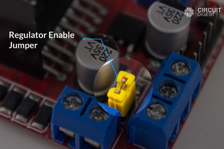
But if you plan to use a DC Motor with a rating (>=12v), it's recommended to provide a separate voltage for the logic circuit via a 5V Pin by removing the jumper that is shown in the above image. Because that regulator can’t able to handle a voltage of more than 12V.
Internal Schematics of L298N Motor Driver Module
If you want to know more about how the L298N motor driver module works, here is the schematic for the L298N driver module. You can utilize the below schematic for reference. Which might be also be helpful if you want to troubleshoot this driver module when it does not work as you expected. If you don't want to get much into the technical working of l298 bridge ic you can skip this section.

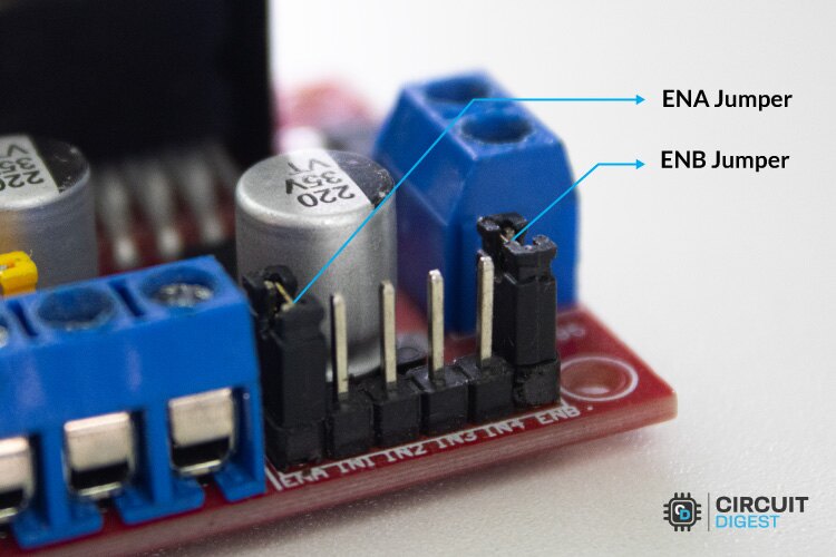
The above H-bridge motor driver circuit is divided into two parts, namely the Motor driver part and the power supply part. In the motor driver unit, you can see the two jumpers namely ENA Jumper and ENB Jumper, which are used for enabling the motor at maximum speed. Here you can find four flyback diodes, which are used to prevent the driver circuit from the back EMF produced by the motors, and the capacitor is placed parallel to the voltage source for stabilizing the voltage.
On the power supply part, you can find the Regulator Enable Jumper, which can be enabled whenever we want to power the logic circuit(Vs) from the Input Supply’s(Vcc) regulated 5V.
How to Use L298N Motor Driver Module
We can use the L298N module in two ways, either by using a Microcontroller like Arduino to control the L298N or standalone without using a microcontroller. In both ways, the operating logic is the same. Below you can see that each motor uses the dedicated three input pins to control its direction of motion as well as its rotation speed.
Motor A Control
Motor B Control
These tables describe the control logic for two DC motors (Motor A and Motor B) using an H-Bridge driver. Each motor is controlled by three input signals: two digital control inputs (IN1, IN2 for Motor A and IN3, IN4 for Motor B) and one PWM (Pulse Width Modulation) enable signal (ENA for Motor A and ENB for Motor B). The motor behavior depends on the combination of these inputs. When both control inputs are LOW (0), the motor enters a braking state. When one input is HIGH (1) and the other is LOW (0), the motor rotates in a specific direction depending on the PWM signal. A PWM signal (0-255) determines the motor's speed. If both control inputs are HIGH (1), the motor is in a braking state. When the enable pin (ENA or ENB) is LOW (0), the motor remains off regardless of the control inputs.
For Motor A, setting IN1 HIGH (1) and IN2 LOW (0) with a PWM signal applied to ENA makes it rotate forward, while setting IN1 LOW (0) and IN2 HIGH (1) with a PWM signal makes it rotate backward. Similarly, for Motor B, setting IN3 HIGH (1) and IN4 LOW (0) with a PWM signal on ENB causes it to rotate forward, while setting IN3 LOW (0) and IN4 HIGH (1) with a PWM signal makes it rotate backward. These control mechanisms allow for precise motor control in robotics and automation applications, enabling directional movement and speed adjustments.
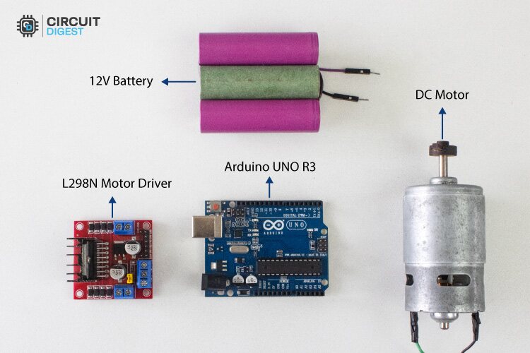
Components Required
Below you can see the list of components needed for interfacing the L298N Driver Module with Arduino.
Arduino UNO R3
L298N Motor Driver Module
12V DC Motor
Battery
Connecting wires
Next, we are going to see how to build the circuit diagram for motor driver interfacing demonstration using the above available components.
Video Tutorial
We have also built a video tutorial showing how to connect the L298N motor driver module with Arduino, which can be found below. You can either follow along with the video or continue reading with this tutorial.
Circuit Diagram for Interfacing L298N Motor Driver with Arduino:
Below, you can find our L298N Motor Driver Interfacing Circuit with Arduino. For demonstration purposes, I am going to utilize only one 12V DC motor in the Motor B pinout side.
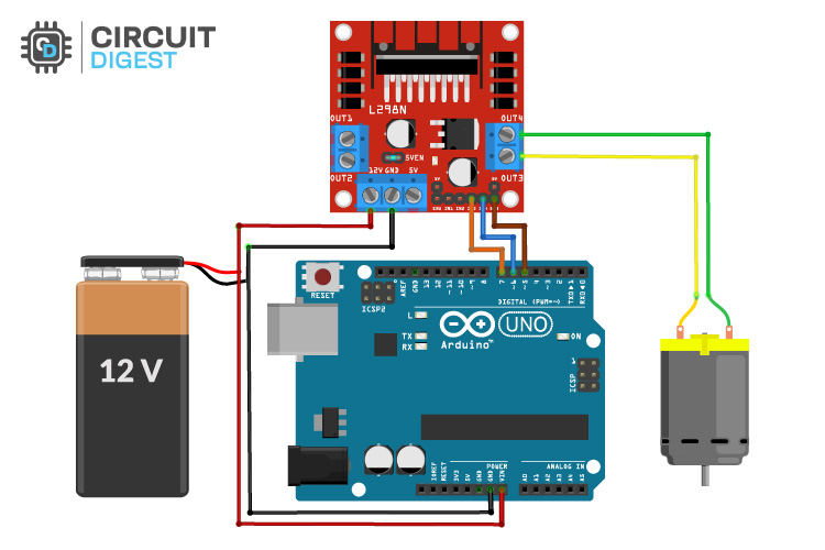
Now let’s discuss the wiring details of this circuit diagram
Here, I have powered the whole setup by using a 12V lithium battery pack which we built earlier.
As we previously discussed, I am using the 12V DC Motor with a 12V DC Source, so, I don’t need to provide a separate 5V power supply for the logic circuit via 5V Pin.
Instead, I can power the logic circuit by enabling the onboard voltage regulator to convert 12V to 5V, with the help of a jumper. If you closely look the the circuit image, I just shorted out those two pins of motor driver with the help of a connecting wire.
I connected the DC motor to the Motor B side of the Module.
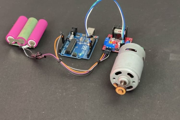
In the above, you can see our actual hardware setup, by using the above circuit diagram as a reference. Now let’s move on to the coding part.
Arduino Code for L298N Motor Driver Module
The main goal of this code is to rotate the motor in both forward and reverse direction with an increase in acceleration from zero to maximum. It also makes the motor to brake before the motor direction gets changed.
Macro Definitions
// Motor B connections
#define ENB 5
#define IN3 7
#define IN4 6
The above macros map the Arduino digital IO pins with the corresponding L298N Driver module pin names. This also represents the pin connection between the driver module and Arduino.
ENB pin connected to D5 pin of Arduino.
IN3 pin connected to D7 pin of Arduino.
IN4 pin connected to D6 pin of Arduino.
Setup() Function
void setup() {
// Set all the motor control pins to outputs
    pinMode(ENB, OUTPUT);
    pinMode(IN3, OUTPUT);
    pinMode(IN4, OUTPUT);

 //Make ensure the motor turned off initially
    off();
}
This setup() function configures the pins ENB, IN3, IN4 as output. After that, it call off() function to turn off the motor initially.
off() Function
void off(){
  analogWrite(ENB, 0);  //Low PWM signal
}
It makes use of the ENB pin as the analog output pin, and sets output to minimum that is 0. It is essential for turning off the motor.
forward() & backward() Function
void forward(){
     digitalWrite(IN3, HIGH);
     digitalWrite(IN4, LOW);
   // Accelerate from zero to maximum speed
    for (int i = 0; i <= 255; i++) {
          analogWrite(ENB, i);
          delay(5);
     }
}
void backward(){
   digitalWrite(IN3, LOW);
   digitalWrite(IN4, HIGH);
   // Accelerate from zero to maximum speed
   for (int i = 0; i <= 255; i++) {
        analogWrite(ENB, i);
        delay(5);
    }
}
forward() function makes the motor rotate in the forward direction with increase in acceleration from minimum to maximum. It makes the motor rotate in forward direction by setting IN3->HIGH and IN4-> LOW. It also increases the speed of the motor gradually by providing the PWM signal in increasing order from 0V(0) to 5V(255) to the ENB pin.
Similarly, the backward() function makes the motor rotate in the reverse direction with an increasing speed by setting the IN3->LOW and IN4->HIGH, It also increases the speed gradually by providing a PWM signal to the ENB pin.
brake() Function
void brake(){
   digitalWrite(IN3, HIGH);
   digitalWrite(IN4, HIGH);
   /*------------------------------
   can also use this to brake/stop the motor
   ---------------------------------
    digitalWrite(IN3, LOW);
    digitalWrite(IN4, LOW);
   ------------------------------*/

}
This brake function makes sure the motor halts suddenly, for that we can make either both IN3, IN4 High or IN3, IN4 Low. Both commands work perfectly.
Ok, now the coding part is over, next we are going to dump the code to see the rotation of the motors.
Working Demonstration
After uploading the code, you can find the motor starts to spin back and forth as shown in the GIF below.
In this working demonstration, you can see the motor get jerked before changing its direction because I utilized the Brake function to stop the motor immediately at a higher RPM.
That’s all about our Interfacing tutor, I hope now you understand how to Interface the Arduino with L298N Driver Module to control the motor. Have fun on rotating the Motors.
GitHub Repo with Code and Circuit
The complete code for Interfacing L298N Motor Driver with Arduino project is given at the bottom of this page. Link to our GitHub repo, where you'll find the source code for this project, is given below.


Frequently Asked Questions:
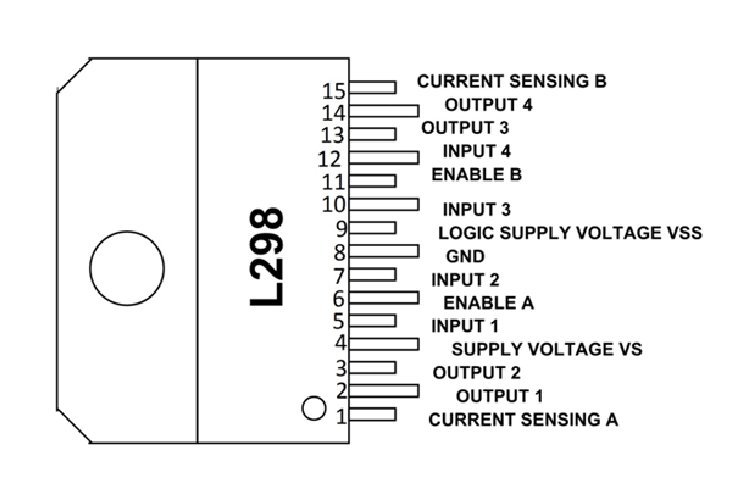
1. L298N IC Pinout?
The L298N motor driver module uses the L298n H bridge IC for driving the motor driver. Below you find the L298N IC Pinout details if you are interested to know how the IC is connected to other components in the module.
2. L298N Driver IC and Driver Module datasheet
Below you can find the link for the L298N Motor Driver IC and Driver module datasheet, where you can find detailed information about its specs, other than what I mentioned in this guide.
L298N Driver IC Datasheet
L298N Driver Module Datasheet
3. Can I control the stepper motor using the L298N Driver?
Yes, the L298N Driver module can control bipolar stepper motors by energizing the coils in the right sequence. This requires the precise control of the IN1/IN2(Motor A) or IN3/IN4(Motor B) pins for handling the stepping sequence.
4. What are the limitations of the L298N to drive the motor?
The main limitation of the L298N is its current handling capability. It may handle up to 2A per channel, but continuous operation at high current causes overheating. Because this IC is based on BJT design. If you need to drive a motor for a long period at a high peak current, it’s recommended to look for a MOSFET-based Driver IC.
5. When do I need to provide 5V(Vss) to the L298N Driver Module?
The L298N Module’s (Vs) pin powers the internal H-Bridge that drives the motor and accepts voltage from 5V to 35V. When supplying more than 12V to the Vs pin, the onboard 5V regulator, which powers the logic circuit, gets overheated.
To avoid this jumper enabling the Onboard 5V regulator should be removed. After removing the jumper, we want to power the logic circuit externally via a Vs (5V) pin.
6. What is the purpose of Jumpers present on the ENA and ENB pins of the L298N Driver Module?
The ENA and ENB pins on the L298N Motor driver module are used to control the speed of motors A and B, respectively. When the jumper is placed, the motor will operate at high speed. Removing the jumper will allow us to control its speed using a PWM signal
7. Can I use the L298N to control the brushless DC motors?
No, the L298N is not suitable for controlling the brushless DC motor. A Brushless DC motor uses a specialized electronic speed controller (ESC) to control it. Basically the L298N is designed for brushed DC and Stepper motors.
Projects using L298N Motor Driver
These projects explore different ways to use the L298N motor driver for controlling motors in robotics and automation. From basic motor control to advanced applications like self-balancing systems and autonomous navigation, they demonstrate how to integrate the L298N with Arduino for various motion-based projects.

Human Following Robot Using Arduino and Ultrasonic Sensor
This project demonstrates how to build a robot that follows a human using ultrasonic sensors for distance measurement and an L298N motor driver to control the motors.

Build your own Mars Rover Robot using Arduino
Inspired by NASA's Mars rovers, this project guides you through creating a rover robot using an Arduino and an L298N motor driver for movement control.
")
Line Follower Robot using Arduino UNO: How to Build (Step-by-Step Guide)
Learn to build a robot that follows a line using infrared sensors and an L298N motor driver to manage the motors.

DIY Arduino Bluetooth Car Controlled by Mobile Application
This project shows how to create a Bluetooth-controlled robot car using an Arduino and an L298N motor driver, allowing control via a smartphone application.

DIY Self Balancing Robot using Arduino
Explore building a self-balancing robot that uses an L298N motor driver to maintain balance and navigate its environment.
Complete Project Code
/*
* Arduino Motor Control Using L298N H-Bridge
* Learn how to control a DC motor using an L298N motor driver with Arduino.
* This tutorial covers motor direction control (forward and backward) and braking.
* Ideal for beginners in robotics and embedded systems.
*/
// Motor B Pin Definitions
#define ENB 5
#define IN3 7
#define IN4 6
// Function to turn off the motor by setting the PWM signal to zero
void off() {
 analogWrite(ENB, 0);  // Disable motor by setting PWM to 0
}
// Function to rotate the motor forward with a gradual speed increase
void forward() {
  digitalWrite(IN3, HIGH);
  digitalWrite(IN4, LOW);
  // Gradually increase speed from 0 to maximum (255)
  for (int i = 0; i <= 255; i++) {
      analogWrite(ENB, i);
      delay(5);
  }
}
// Function to rotate the motor backward with a gradual speed increase
void backward() {
  digitalWrite(IN3, LOW);
  digitalWrite(IN4, HIGH);
  // Gradually increase speed from 0 to maximum (255)
  for (int i = 0; i <= 255; i++) {
      analogWrite(ENB, i);
      delay(5);
  }
}
// Function to stop the motor by applying a braking mechanism
void brake() {
  digitalWrite(IN3, HIGH);
  digitalWrite(IN4, HIGH);

  /*
  Alternative method to stop the motor:

  digitalWrite(IN3, LOW);
  digitalWrite(IN4, LOW);

  */
}
void setup() {
  // Configure motor control pins as outputs
  pinMode(ENB, OUTPUT);
  pinMode(IN3, OUTPUT);
  pinMode(IN4, OUTPUT);

  // Ensure the motor remains off at startup
  off();
}
void loop() {
  // Motor sequence: Forward -> Stop -> Backward -> Stop
  forward();
  brake();
  delay(500);
  backward();
  brake();
  delay(500);
}
