
The planet Mars has captivated our imagination for centuries, and the idea of sending rovers to explore its surface has fueled our curiosity even further. In this project, we will delve into the exciting world of robotics and demonstrate how to build an Arduino-based Mars rover capable of traversing various terrains. So, fasten your seatbelt as we embark on this thrilling journey of constructing our very own Mars rover.
In this article, our focus is on creating an Arduino Bluetooth-controlled Mars rover. Arduino proves to be a valuable and cost-effective option for hobbyists, acting like a miniature computer. This guide aims to provide a clear step-by-step explanation of building a rover chassis to its programming to its testing. Our primary task involves coding instruction, which is written in the C or C++ programming language. The Arduino microcontroller compiles and executes the code, enabling the rover to function according to our desired specifications.
We also have a dedicated Arduino robotics section, where you can find all kinds of Arduino robotics projects like line follower robot, fire fighting robot, robotic arm, self balancing robot, etc.
Understanding Mars Rover Design
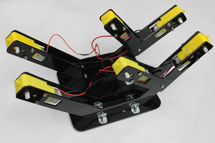
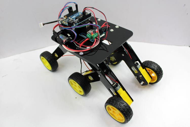
Before we dive into the technical aspects, let’s take a moment to understand the design considerations of a Mars rover. A typical Mars rover needs to navigate a challenging landscape on the Martian surface. To achieve this, we will focus on building a rover with the 6-wheels drive system with appropriate suspension ensure optimal mobility and stability for the rover.
The rover chassis serves as the foundation for the entire vehicle. It needs to be sturdy, durable, and capable of traversing different terrains and should also accommodate the placement of various electronic components, such as the Arduino board, power supply, and motor control modules.
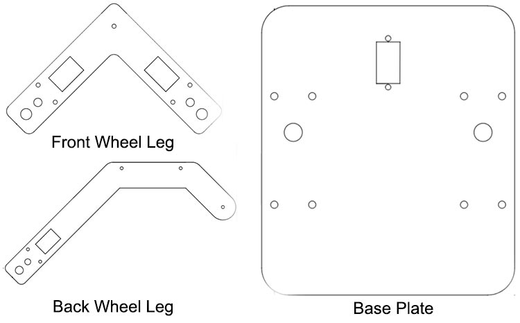
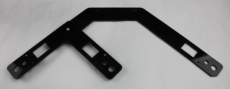
I created acrylic chassis parts using SolidWorks and performed laser cutting to construct my Mars rover.
I am attaching the.dxf files for the Mars rover project, which you can utilize for laser cutting. The video will demonstrate the assembly process for the Mars rover.
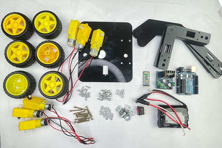
Necessary Components Needed for Mars Rover
Mars rover acrylic cutting chassis
6 BO motors and wheels
Arduino Uno
L298n motor driver module
HC-05 Bluetooth module
12V Li-ion battery with connector
L clamp (8 nos.)
M4 10mm nuts and bolts (8 nos.)
M3 10mm nuts and bolts (12 nos.)
M3 30mm nuts and bolts (12 nos.)
Switch and connecting wires
L298N Motor Driver Module
The L298N motor driver module is a popular motor driver module commonly used in robotics and electronics projects. The module is based on the L298n integrated circuit, it has two H-bridge circuits, one for each motor channel, which enables bi-directional control of the motors. By providing appropriate logic signals to the module’s control pins, you can control the motor’s speed and direction.
Since we are not using the PWM signal generated by the Arduino to control the speed of the motors, they will operate at their maximum speed. This is because we keep the ENA and ENB pins, which correspond to the PWM control, in a fixed state on the board. Therefore, the main purpose of the motor driver module in this setup is to change the direction of rotation of the motors. This capability enables the robot to move in all four directions, including forward, backward, left, and right.
L298N Motor Driver Pinout
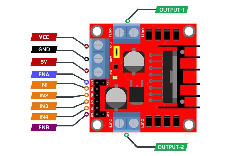
The L298N motor driver module has a specific pinout that corresponds to its various functionalities. Here is the pinout description of the L298N motor driver module. If you are completely new to this motor driver module, check out our article on how to use L298N with Arduino for a detailed understanding.
VCC This pin is used to connect an external power source (up to 12V) to power the motors.
GND This pin is the ground connection for the module and should be connected to the ground of the power source and the control signal source (Arduino).
5V This pin provides a regulated 5V output that can be used to power external components or provide logic voltage to the control signal source.
ENA & ENB This pin is used to enable or disable the motor connected to Channel A and Channel B. It is responsible for controlling the speed of the motor through PWM (Pulse Width Modulation) signals.
IN1, IN2, IN3, IN4 This input pin is used to control the direction of rotation for the motor connected to Channel A, similarly IN3 & IN4 for Channel B. By providing appropriate logic levels (HIGH or LOW), you can set the desired direction. This pins are connected to Arduino digital pins for receiving (HIGH or LOW) signal.
OUT-1 & OUT-2 The pin mentioned is intended for connecting the motors. Specifically, one motor should be connected to OUT-1 & OUT-2 while the other motor should be connected to OUT-3 & OUT-4 . It is important to note that the motors can be connected within a voltage range of 5V to 35V. However, it's worth considering that there will be an approximate 2-volt reduction in the output voltage compared to the voltage applied to the Vcc pin.
HC-05 Bluetooth Module
The HC-05 is a widely used Bluetooth module that provides a convenient and reliable way to add wireless communication capabilities to electronic devices. It supports serial communication via UART (Universal Asynchronous Receiver-Transmitter) protocol.
The HC-05 module supports the Bluetooth version 2.0 specification and can be configured as a Master or Slave device through AT commands, depending on the desired application. In the Master mode, it can initiate connections with other Bluetooth devices, while in the Slave mode, it can accept incoming connections.
HC-05 Pinout
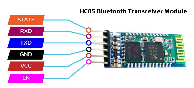
The HC-05 Bluetooth module has a specific pinout that corresponds to its various functionalities. Here is the pinout description of the HC-05 Bluetooth module.
VCC This pin is used to provide power to the module. It typically operates at a voltage range of 3.3V to 6V.
GND This pin is the ground connection for the module and should be connected to the ground of the power source and the control signal source.
TXD This pin is the transmit data pin and is used to send data from the module to another device. It should be connected to the receive pin (RX) of the receiving device.
RXD This pin is the receive data pin and is used to receive data from another device. It should be connected to the transmit pin (TX) of the transmitting device.
STATE This pin is an optional pin that can be used to check the state of the module. It can be configured to provide information about the module's connection status or other relevant information.
EN This pin is used to enable or disable the module (Command & Data mode). When this pin is pulled HIGH (3.3V or 5V), the module is enabled (command mode), and when it is pulled LOW (0V or GND), the module is disabled (data mode).
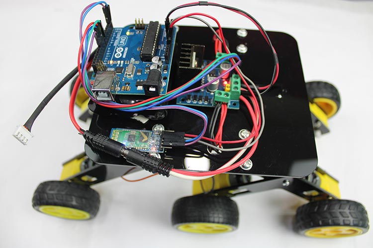
Assemble the Mars Rover Chassis
We have utilized an acrylic sheet cut with a laser to create a chassis for our project. The sheet has been precisely cut to accommodate all the necessary fittings and components, allowing for easy assembly using screwdrivers.
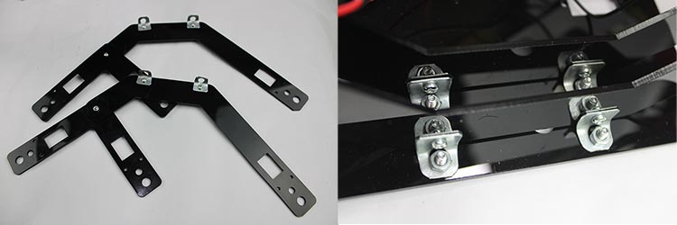
Connect back leg with front leg with the help of M4 10mm nuts and bolts
Connect the pair of front and back legs with the base plate with the help of an L clamp with M3, M4 10mm nuts and bolts.
Attached the motors with both legs to its appropriate location with M3 30mm nuts and bolts.
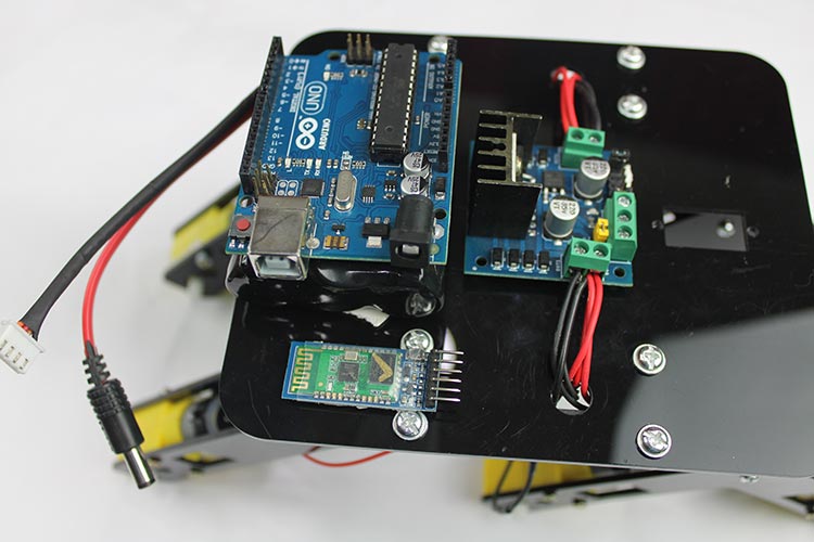
Placed all the electronics components to its suitable location with double side tape.
Arduino Bluetooth Controlled Mars Rover Circuit Diagram
Here is the schematic of a Bluetooth-controlled Mars rover. In this design, we have a total of six motors, with three motors connected in parallel on the right side and three motors connected in parallel on the left side. This configuration allows all three motors on each side to operate synchronously, running at the same speed and in the same direction. By connecting them in parallel, we ensure that they receive the same control signals and power supply. This arrangement enables efficient and coordinated movement for the rover, enhancing its maneuverability and stability.

Connections:
Arduino and HC-05 Bluetooth Module:
Connect the TX pin of the Bluetooth module to the RX pin (usually digital pin 0) of the Arduino.
Connect the RX pin of the Bluetooth module to the TX pin (usually digital pin 1) of the Arduino.
Connect the VCC and GND pins of the Bluetooth module to the appropriate power (+5V) and ground pins on the Arduino.
Arduino and Motor Driver Module:
Connect the digital output pins of the Arduino (digital pins 10, 9, 8, and 7) to the appropriate input pins (IN1, IN2, IN3, and IN4) on the motor driver module.
Connect the ENA and ENB pins of the motor driver module to the on board High state pin with the help of female header.
Connect the OUT1, OUT2, OUT3, and OUT4 pins of the motor driver module to the appropriate terminals of the motors.
Connect the VCC (+5V) and GND pins of the motor driver module to the appropriate power (Vin) and ground (GND) connections on the Arduino.
Power Supply:
Connect the positive terminal of the power supply to the +12V input of the motor driver module.
Connect the negative terminal of the power supply to the GND pin of the motor driver module.
Connect the GND pin of the Arduino to the GND pin of the motor driver module.
Code Explanation
Here is the simple Bluetooth control Mars rover code that you can use for your project.
Pin configuration: The pins on the Arduino board that are connected to the motor driver module and other components are defined. This step ensures that the correct pins are used for motor control and other operations.
We have defined the IN1, IN2, IN3 & IN4 pins as 10,9,8 & 7 digital pins of the Arduino. This pins are connected to input pins of motor driver module.
 int state=0;
const int motorpin11=10;  // L298n #NI1
const int motorpin12=9;   // L298n #NI2
const int motorpin21=8;   // L298n #NI3
const int motorpin22=7;   // L298n #NI4
Setup: The setup function runs only once at the beginning of the code execution. It is responsible for configuring the communication protocols, setting the pin modes, and initializing variables
Within the setup() function, we begin by initializing the hardware serial communication with a baud rate of 9600. This allows the Arduino to establish communication with external devices, such as the Bluetooth module, at the specified data transmission rate.
Next, we set the pin modes for the direction control pins used for motor control. These pins are configured to control the movement and direction of the motors. By setting them initially to LOW, we ensure that the motors are in a halted state at the start of the program execution. This prevents any unintended movement of the motors before receiving any commands or instructions.
Initializing the hardware serial communication and setting the appropriate pin modes are crucial steps in preparing the Arduino for proper motor control and ensuring that the initial motor state is controlled and stationary.
void setup() {
  Serial.begin(9600);
  pinMode(motorpin11,OUTPUT);
  pinMode(motorpin12,OUTPUT);
  pinMode(motorpin21,OUTPUT);
  pinMode(motorpin22,OUTPUT);
  digitalWrite(motorpin11,LOW);
  digitalWrite(motorpin12,LOW);
  digitalWrite(motorpin21,LOW);
  digitalWrite(motorpin22,LOW);
} Loop: The loop function runs continuously after the setup is complete. It includes the main logic of the program, defining the behavior of the Mars Rover based on the received commands.
The loop() function continuously checks for incoming commands from the Bluetooth module. Depending on the received command, the rover will move forward, backward, turn left, turn right, or stop.
The code listens for incoming Bluetooth signals and receives commands from a paired device. This could include instructions for moving forward, backward, turning left or right, or stopping the rover.
  void loop()
  { if (Serial.available()>0)
  state=Serial.read();
{
The received commands are translated into appropriate motor control signals. The code sends the necessary signals to the motor driver module, adjusting the directions according to the instructions.
 if (state=='F') {
    digitalWrite(motorpin11,HIGH);
    digitalWrite(motorpin12,LOW);     // Forward motion of rover
    digitalWrite(motorpin21,HIGH);
    digitalWrite(motorpin22,LOW);
  }
   else if(state=='B') {
      digitalWrite(motorpin11,LOW);
      digitalWrite(motorpin12,HIGH);   // Backward motion of rover
      digitalWrite(motorpin21,LOW);
      digitalWrite(motorpin22,HIGH);
      }
      else if(state=='S') {
        digitalWrite(motorpin11,LOW);
        digitalWrite(motorpin12,LOW);     // Stop
        digitalWrite(motorpin21,LOW);
        digitalWrite(motorpin22,LOW);
        }
        else if(state=='L') {
        digitalWrite(motorpin11,HIGH);
        digitalWrite(motorpin12,LOW);     // Left motion of rover
        digitalWrite(motorpin21,LOW);
        digitalWrite(motorpin22,HIGH);
        }
        else if(state=='R')
      {
        digitalWrite(motorpin11,LOW);
        digitalWrite(motorpin12,HIGH);     // Right motion of rover
        digitalWrite(motorpin21,HIGH);
        digitalWrite(motorpin22,LOW);
        }
        else if(state=='l')
      {
        digitalWrite(motorpin11,LOW);
        digitalWrite(motorpin12,HIGH);    // Backward Left motion of rover
        digitalWrite(motorpin21,HIGH);
        digitalWrite(motorpin22,LOW);
        }
        else if(state=='r')
      {
        digitalWrite(motorpin11,HIGH);
        digitalWrite(motorpin12,LOW);     // Backward Right motion of rover
        digitalWrite(motorpin21,LOW);
        digitalWrite(motorpin22,HIGH);
        }
  }}
The received data is being compared using if and else if statements, allowing for conditional execution of specific statements based on the evaluation of these conditions.
Within these conditional statements, we have defined seven different movement functions that correspond to various actions for the Mars Rover. These functions are called inside the if statements based on the specific conditions met. Each function is responsible for controlling a specific movement, such as moving forward, backward, turning left or right, stopping, backward left and backward right.
By organizing the code in this way, we can modularize the functionality and make it easier to understand and maintain. The conditional statements ensure that the appropriate movement function is executed when the corresponding condition is met based on the received data.
In summary, the if and else if statements enable the code to evaluate the received data and execute the corresponding movement function based on the condition met, facilitating precise control and maneuverability of the Mars Rover.
Setup the Android App for controlling Mars Rover
To connect the Bluetooth-controlled car with your phone, follow these steps:
Open the "Bluetooth RC Car" app on your Android device. Please note that currently, this app is only available for Android users.
Turn on the Bluetooth on your phone by going to your phone's settings.
Connect your phone to the HC-05 Bluetooth module. If you have a new HC-05 module, there is an additional step before connecting.
Go to the Bluetooth settings on your phone.
Search for Bluetooth devices.
You will find a Bluetooth device named HC-05.
Pair the Bluetooth device with your phone by selecting it.
During the pairing process, you will be prompted to enter a password.
The default password for HC-05 is usually either 1234 or 0000.
Enter the password and proceed with the pairing process.
Once the pairing is successful, your Bluetooth-controlled Mars rover is now connected to your Android device.

By following these steps, you can establish a connection between your phone and the Bluetooth module of the Mars rover, allowing you to control the wirelessly using the "Bluetooth RC Car" app.
Conclusion
Congratulations! You have successfully built your Arduino-based Mars rover. Now, it's time to let it roam and explore. Take your rover to various terrains, conduct experiments, and gather valuable data. Control it wirelessly using a smartphone or other Bluetooth-enabled devices, and observe how it maneuvers through the challenges.
Building an Arduino Mars rover offers a thrilling opportunity to delve into robotics, electronics, and programming. It allows us to simulate the exploration of distant planets and sparks our curiosity about the mysteries of the universe. So, grab your tools, unleash your creativity, and embark on this exciting journey of building and exploring with your very own Mars rover!
Complete Project Code
int state=0;
const int motorpin11=10;  // L298n #NI1
const int motorpin12=9;   // L298n #NI2
const int motorpin21=8;   // L298n #NI3
const int motorpin22=7;   // L298n #NI4
void setup() {
  pinMode(motorpin11,OUTPUT);
  pinMode(motorpin12,OUTPUT);
  pinMode(motorpin21,OUTPUT);
  pinMode(motorpin22,OUTPUT);
  digitalWrite(motorpin11,LOW);
  digitalWrite(motorpin12,LOW);
  digitalWrite(motorpin21,LOW);
  digitalWrite(motorpin22,LOW);
  Serial.begin(9600);
  }
  void loop()  {
  if (Serial.available()>0)
  state=Serial.read();
  {
 if (state=='F')
     {
    digitalWrite(motorpin11,HIGH);
    digitalWrite(motorpin12,LOW);     // Forward motion of rover
    digitalWrite(motorpin21,HIGH);
    digitalWrite(motorpin22,LOW);
  }
   else if(state=='B')
    {
      digitalWrite(motorpin11,LOW);
      digitalWrite(motorpin12,HIGH);   // Backward motion of rover
      digitalWrite(motorpin21,LOW);
      digitalWrite(motorpin22,HIGH);
      }
      else if(state=='S')
      {
        digitalWrite(motorpin11,LOW);
        digitalWrite(motorpin12,LOW);     // Stop
        digitalWrite(motorpin21,LOW);
        digitalWrite(motorpin22,LOW);
        }
        else if(state=='L')
      {
        digitalWrite(motorpin11,HIGH);
        digitalWrite(motorpin12,LOW);     // Left motion of rover
        digitalWrite(motorpin21,LOW);
        digitalWrite(motorpin22,HIGH);
        }
        else if(state=='R')
      {
        digitalWrite(motorpin11,LOW);
        digitalWrite(motorpin12,HIGH);     // Right motion of rover
        digitalWrite(motorpin21,HIGH);
        digitalWrite(motorpin22,LOW);
        }
        else if(state=='l')
      {
        digitalWrite(motorpin11,LOW);
        digitalWrite(motorpin12,HIGH);    // Backward Left motion of rover
        digitalWrite(motorpin21,HIGH);
        digitalWrite(motorpin22,LOW);
        }
        else if(state=='r')
      {
        digitalWrite(motorpin11,HIGH);
        digitalWrite(motorpin12,LOW);     // Backward Right motion of rover
        digitalWrite(motorpin21,LOW);
        digitalWrite(motorpin22,HIGH);
        }
  }}
Comments
Here's my Mars Rover, a 1/4 scale version of Mars Perseverance Rover. Designed by How To Mechantronics, I built it last year. Uses an Arduino Mega, has 6 motors, 4 steering servos and a stepper and servo for the camera. Operated by Flysky remote control using iBus.JPG)

Thank you for providing this update