

After being inspired by RYNO motors and other self-balancing scooters from Segway, I always wanted to build something of my own Arduino Segway Robot. Thinking for a while, I decided to build a Self Balancing Robot using Arduino. This way I would be able to grasp the underlying concept behind all these scooters and also learn how the PID algorithm works.
Once I started building, I realised that this bot is a bit of a challenge to build. There are so many options to select from, and hence the confusions start right from selecting the motors and remains till tuning PID values. And there are so many things to consider, like the type of battery, the position of the battery, wheel grip, type of motor driver, maintaining the CoG (Centre of gravity) and much more. So let's face it, in this tutorial, I will document my experience in building the Arduino self balancing robot.
But let me break it to you, once you build it, you will agree that it’s not as hard as it sounds. So let’s face it, in this tutorial, I will document my experience in building the self-balancing robot Arduino code. You might be an absolute beginner who is just getting started, or you might have landed up here after a long frustration of not getting your bot to work. This place aims to be your final destination. So let’s get started......
Self Balancing Robot using Arduino - Quick Overview
Build Time: 8-12 hours | Cost: $30-50 | Difficulty: Intermediate-Advanced
What You'll Learn: PID algorithm, MPU6050 sensor integration, DC motor control, I2C communication
Applications: Robotics education, Balance control systems, Autonomous navigation, DIY personal transport
Table of Contents
Essential Components for Arduino Self Balancing Robot Circuit
Before I tell you all the options for building the bot, let me list the items that I have used in this self balancing robot using Arduino project:
- Arduino UNO
- Geared DC motors (Yellow coloured) – 2Nos
- L298N Motor Driver Module
- MPU6050
- A pair of wheels
- 7.4V Li-ion Battery
- Connecting wires
- 3D Printed Body
You can mix and choose any of the above components based on availability to make your self-balancing robot kit. Just make sure that the components fit the following criteria.
You can mix and choose any of the above components based on availability to make your own self balancing robot kit, just make sure that the components fit the following criteria.
Component Selection Guide for Self Balancing Robot Using Arduino Uno
Controller: For this self balancing robot using Arduino Uno The controller that I have used here is Arduino UNO. Why? Because it is simply easy to use. You can also use an Arduino Nano or Arduino mini, but I would recommend you stick with UNO since we can program it directly without any external hardware.
Motors: The best choice of motor that you can use for an Arduino self balancing robot without a doubt, will be a Stepper motor. But to keep things simple, I have used a DC gear motor. Yes, it is not mandatory to have a stepper; the bot works fine with these cheap, commonly available yellow coloured DC gear motors as well.
Motor Driver: If you have selected the DC gear motors like mine, then you can either use the L298N driver module like me, or even a L293D should work just fine. Learn more about controlling a DC motor using L293D and Arduino.
Wheels: Do not underestimate these guys; I had a tough time figuring out that the problem was with my wheels. So make sure your wheels have a good grip on the floor you are using. Watch closely, your grip should never allow your wheels to skid on the floor.
Accelerometer and Gyroscope: The best choice of Accelerometer and Gyroscope for your Arduino self balancing robot, your bot will be the MPU6050. So do not attempt to build one with a normal Accelerometer like ADXL345 or something like that, it just won’t work. You will know why at the end of this article. You can also check our dedicated article on using MPU6050 with Arduino.
Battery: We need a battery that is as light as possible, and the operating voltage should be more than 5V so that we can power our Arduino directly without a boost module. So the ideal choice will be a 7.4V Li-polymer battery. Here, since I had a 7.4V Li-ion battery readily available, I have used it. But remember, a Li-po is advantageous than a Li-ion.
Chassis: Another place where you should not compromise is with your bot's chassis. You can use cardboard, wood, plastic anything that you are good with. But, just make sure the chassis is sturdy and should not wiggle when the bot is trying to balance. I have designed my chassis on SolidWorks, inferring from the other bots, and 3D printed it. If you have a printer, then you can also print the design; the design files will be attached in the upcoming heading.
Building Your Arduino Self Balancing Robot: 3D Printing & Assembly Guide
If you have decided to 3D print the same chassis that I am using to build my bot, then the STL files can be downloaded from Thingiverse. I have also added the design files along with it, so you can also modify it as per your personal preferences.
The parts have no overhanging structures, so you can easily print them without any supports, and an infill of 25% will work fine. The designs are pretty plain, and any basic printer should be able to handle them with ease. I used the Cura software to slice the model and printed using my Tevo Tarantula; the settings are shown below.
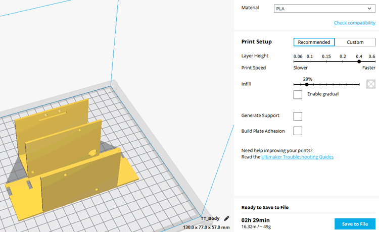
You would have to print the body part as well as four motor mounting parts. The assembly is pretty straightforward; use 3mm nuts and bolts to secure the motor and boards in place. After assembling it should look something like this shown in the picture below.
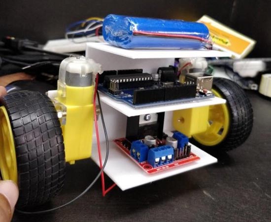
The actual design was planned with the L298N drive module in the bottom rack, the Arduino and battery on top of it, as shown above. If you are following the same order, you can directly screw the board through the holes provided and use a wire tag for the Li-po battery. This arrangement should also work, except for the super plain wheels, which I had to change later.
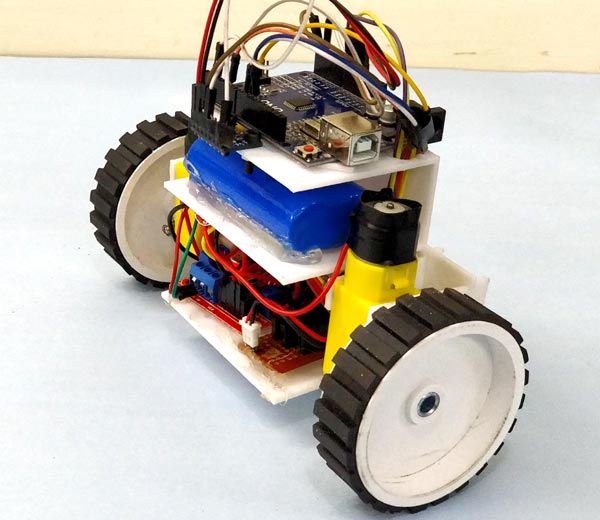
In my bot, I have swapped the position of the battery and Arduino UNO board for ease of programming and also had to introduce a perf board for completing the connections. So my bot did not look as I planned in the initial stage. After completing the wiring, programming, testing and everything, my two-wheel balancing robot finally looks like this

Self Balancing Robot Circuit Diagram Using Arduino Uno
Making the connections for this Arduino based Self balancing Robot is pretty simple. This is a self balancing robot using Arduino and MPU6050, so we have to interface the MPU6050 with Arduino and connect the motors through the Motor driver module. The whole setup is powered by the 7.4V Li-ion battery. The circuit diagram for the same is shown below.

The self balancing robot circuit diagram above shows the whole connections between Arduino Uno, MPU6050 sensor, and L298N motor driver to build a self balancing robot. This Arduino self balancing robot circuit is designed to provide better performance and simple troubleshooting.
Arduino Uno Pin Connections for Self Balancing Robot Using MPU6050
The Arduino and the L298N Motor driver module are directly powered through the Vin pin and the 12V terminal, respectively. The on-board regulator on the Arduino board will convert the input 7.4V to 5V, and the ATmega IC and MPU6050 will be powered by it. The DC motors can run from a voltage of 5V to 12V. But we will be connecting the 7.4V positive wire from the battery to the 12V input terminal of the motor driver module. This will make the motors operate with 7.4V. The following table will list how the MPU6050 and L298N motor driver module are connected to the Arduino.
Component Pin | Arduino Pin |
MPU6050 | |
Vcc | +5V |
Ground | Gnd |
SCL | A5 |
SDA | A4 |
INT | D2 |
L298N | |
IN1 | D6 |
IN2 | D9 |
IN3 | D10 |
IN4 | D11 |
The MPU6050 communicates with Arduino through the I2C interface, so we use the SPI pins A4 and A5 of Arduino. The DC motors are connected to PWM pins D6, D9, D10 and D11, respectively. We need to connect them to PWM pins because we will be controlling the speed of the DC motor by varying the duty cycle of the PWM signals. If you are not familiar with these two components, then it is recommended to read through the MPU6050 Interfacing and L298N Motor Driver tutorial.
Complete Self-Balancing Robot Arduino Code with PID Implementation
Now we have to program our Arduino UNO board to balance the robot. This is where all the magic happens; the concept behind it is simple. We have to check if the bot is leaning towards the front or the back using the MPU6050, and then if it’s leaning towards the front, we have to rotate the wheels in the forward direction, and if it is leaning towards the back, we have to rotate the wheels in the reverse direction.
Understanding the PID Algorithm in Self-Balancing Robot Arduino Code
At the same time, we also have to control the speed at which the wheels are rotating. If the bot is slightly disoriented from the centre position, the wheels rotate slowly, and the speed increases as it gets further away from the centre position. To achieve this logic, we use the PID algorithm, which has the centre position as the set-point and the level of disorientation as the output.
To know the current position of the bot, we use the MPU6050, which is a 6-axis accelerometer and gyroscope sensor combined. In order to get a reliable value of position from the sensor, we need to use the values of both the accelerometer and gyroscope, because the values from the accelerometer have noise problems, and the values from the gyroscope tend to drift with time. So we have to combine both and get the value of yaw, pitch and roll of our robot, of which we will use only the value of yaw.
Sounds a bit like head reeling, right? But worry not, thanks to the Arduino community, we have readily available libraries that can perform the PID calculation and also get the value of yaw from the MPU6050. The library is developed by br3ttb and jrowberg, respectively. Before proceeding, download their libraries from the following link and add them to your Arduino library directory.
https://github.com/br3ttb/Arduino-PID-Library/blob/master/PID_v1.h
https://github.com/jrowberg/i2cdevlib/tree/master/Arduino/MPU6050
Now that we have the libraries added to our Arduino IDE. Let’s start programming for our Self balancing Robot. Like always, the complete code for the MPU6050 balancing robot is given at the end of this page; here, I am just explaining the most important snippets in the code. A mentioned earlier, the code is built on top of the MPU6050 example code. We are just going to optimise the code for our purpose and add the PID and control technique for our self balancing robot.
First, we include the libraries that are required for this program to work. They include the in-built I2C library, PID Library and MPU6050 Library that we just downloaded.
#include "I2Cdev.h"
#include <PID_v1.h> //From https://github.com/br3ttb/Arduino-PID-Library/blob/master/PID_v1.h
#include "MPU6050_6Axis_MotionApps20.h" //https://github.com/jrowberg/i2cdevlib/tree/master/Arduino/MPU6050
Then we declare the variables that are required to get the data from the MPU6050 sensor. We read both the gravity vector and quaternion values and then compute the yaw, pitch and roll values of the bot. The float array ypr[3] will hold the final result.
// MPU control/status vars
bool dmpReady = false;  // set true if DMP init was successful
uint8_t mpuIntStatus;   // holds actual interrupt status byte from MPU
uint8_t devStatus;      // return status after each device operation (0 = success, !0 = error)
uint16_t packetSize;    // expected DMP packet size (default is 42 bytes)
uint16_t fifoCount;     // count of all bytes currently in FIFO
uint8_t fifoBuffer[64]; // FIFO storage buffer
// orientation/motion vars
Quaternion q;           // [w, x, y, z]         quaternion container
VectorFloat gravity;    // [x, y, z]            gravity vector
float ypr[3];           // [yaw, pitch, roll]   yaw/pitch/roll container and gravity vector
Next comes the very important segment of the code, and this is where you will be spending a long time tuning for the right set of values. If your robot is built with a very good centre of gravity and the components are symmetrically arranged (which in most cases is not) then the value of your set-point will be 180. Else, connect your bot to the Arduino serial monitor and tilt it till you find a good balancing position, read the value displayed on the serial monitor, and this is your set point value. The value of Kp, Kd and Ki has to be tuned according to your bot. No two identical bots will have the same values of Kp, Kd and Ki, so there is no escaping from it. Watch the video at the end of this page to get an idea of how to adjust these values.
/*********Tune these 4 values for your BOT*********/
double setpoint= 176; //set the value when the bot is perpendicular to ground using serial monitor.
//Read the project documentation on circuitdigest.com to learn how to set these values
double Kp = 21; //Set this first
double Kd = 0.8; //Set this secound
double Ki = 140; //Finally set this
/******End of values setting*********/
In the next line, we initialise the PID algorithm by passing the input variables input, output, set point, Kp, Ki and Kd. Out of these, we have already set the values of set-point Kp, Ki and Kd in the above snippet of code. The value of input will be the current value of yaw that is read from the MPU6050 sensor, and the value of output will be the value that is calculated by the PID algorithm. So basically, the PID algorithm will give us an output value which should be used to correct the Input value to bring it close to the set point.
PID pid(&input, &output, &setpoint, Kp, Ki, Kd, DIRECT);
Inside the void setup function, we initialise the MPU6050 by configuring the DMP (Digital Motion Processor). This will help us in combining the Accelerometer data with the Gyroscope data and provide a reliable value of Yaw, Pitch and Roll. We will not go very deep into this since it will be far beyond the topic. Anyhow, one segment of code that you have to look up in the setup function is the gyro offset values. Each MPU6050 sensor has its values of offsets. You can use this Arduino sketch to calculate the offset value of your sensor and update the following lines accordingly in your program.
    // supply your own gyro offsets here, scaled for min sensitiviy
    mpu.setXGyroOffset(220);
    mpu.setYGyroOffset(76);
    mpu.setZGyroOffset(-85);
    mpu.setZAccelOffset(1688);
We also have to initialise the Digital PWM pins that we are using to connect our motors to. In our case, it is D6, D9, D10 and D11. So we initialise these pins as output pins and make them LOW by default.
//Initialise the Motor outpu pins
    pinMode (6, OUTPUT);
    pinMode (9, OUTPUT);
    pinMode (10, OUTPUT);
    pinMode (11, OUTPUT);
//By default turn off both the motors
    analogWrite(6,LOW);
    analogWrite(9,LOW);
    analogWrite(10,LOW);
    analogWrite(11,LOW);
Inside the main loop function, we check if the data from the MPU6050 is ready to be read. If yes, then we use it to compute the PID value and then display the input and output values of the PID on the serial monitor just to check how the PID is responding. Then, based on the value of the output, we decide if the bot has to move forward or backwards or stand still.
Since we assume that the MPU6050 will return 180 when the bot is upright. We will get positive correction values when the bot is falling towards the front, and we will get values in negative if the bot is falling towards the back. So we check for this condition and call the appropriate functions to move the bot forward or backwards.
    while (!mpuInterrupt && fifoCount < packetSize)
    {
        //no mpu data - performing PID calculations and output to motors
        pid.Compute();

        //Print the value of Input and Output on serial monitor to check how it is working.
        Serial.print(input); Serial.print(" =>"); Serial.println(output);

        if (input>150 && input<200){//If the Bot is falling

        if (output>0) //Falling towards front
        Forward(); //Rotate the wheels forward
        else if (output<0) //Falling towards back
        Reverse(); //Rotate the wheels backward
        }
        else //If Bot not falling
        Stop(); //Hold the wheels still
    }
The PID output variable also decides how fast the motor has to be rotated. If the bot is just about to fall, then we make a minor correction by rotating the wheel slowly. If these minor corrections didn't work and still if the bot is still falling, we increase the speed of the motor. The value of how fast the wheels rotate will be decided by the PI algorithm. Note that for the Reverse function, we have multiplied the value of the output by -1 so that we can convert the negative value to positive.
void Forward() //Code to rotate the wheel forward
{
    analogWrite(6,output);
    analogWrite(9,0);
    analogWrite(10,output);
    analogWrite(11,0);
    Serial.print("F"); //Debugging information
}
void Reverse() //Code to rotate the wheel Backward
{
    analogWrite(6,0);
    analogWrite(9,output*-1);
    analogWrite(10,0);
    analogWrite(11,output*-1);
   Serial.print("R");
}
void Stop() //Code to stop both the wheels
{
    analogWrite(6,0);
    analogWrite(9,0);
    analogWrite(10,0);
    analogWrite(11,0);
    Serial.print("S");
}
Arduino Self Balancing Robot Testing & PID Tuning Guide
Once you are ready with the hardware, you can upload the self-balancing robot Arduino code to your Arduino board. Make sure the connections are proper since we are using a Li-ion battery; extreme caution is needed. So double-check for short circuits and ensure that the terminals won’t come into contact even if your bot experiences some small impacts. Power up your module and open your serial monitor. If your Arduino can communicate with MPU6050 successfully and if everything is working as expected, you should see the following screen.
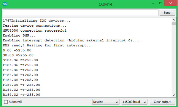
Here we see the input and output values of the PID algorithm in the format input => output. If the bot is perfectly balanced, the value of output will be 0. The input value is the current value from the MPU6050 sensor. The alphabet “F” represents that the bot is moving forward, and “R” represents that the bot is moving in reverse.
During the initial stages of PID, I recommend leaving your Arduino cable connected to the bot so that you can easily monitor the values of input and output, and also it will be easy to correct and upload your program for Kp, Ki and Kd values. The video below shows the complete working of the bot and also shows how to correct your PID values.
Technical Summary And GitHub Repository
A Technical Summary gives a summary of the purpose, development and main outcomes of the project. The GitHub Repository give you the complete source code and documentation. It provides a quick understanding and hands-on implementation for users and contributors.


Frequently Asked Questions on Arduino Self Balancing Robot
⇥ 1. Can I use Arduino Nano instead of Arduino Uno for this self balancing robot?
Yes, Arduino Nano is fine with this self balancing robot Arduino code. Nevertheless, Arduino Uno is more suitable for beginners as it is simpler to program and debug without extra hardware.
⇥ 2. Why isn't my self balancing robot using Arduino Uno balanced?
Common problems are undesired PID values, bad grip for wheels, poorly placed center of gravity, and defective sensor calibration. Check if your MPU6050 is calibrated properly, and then start adjusting the parameters of your PID carefully.
⇥ 3. How do I find my robot's correct setpoint value?
Plug your robot into the Arduino IDE serial monitor and physically tilt the robot to find the balanced position. Then, see the value displayed. Use this value as your setpoint to put into the Arduino self balancing robot code.
⇥ 4. What is the best way to tune PI values for my robot?
For startup tuning, I started with Kp=21, and adjusted until the robot started to respond to tilts. Then added Kd=0.8 to help smooth out some oscillation. For just steady state error correction, I then just added Ki=140. With these k values, some steady state error correction is done. All robots require individual tuning.
⇥ 5. Why does my robot function with a USB connection, but not with outside power?
This is a sign of power supply problems. You should check all power connections or make sure your 7.4V battery can supply greater than or equal to the combined current draw of your motors and Arduino. A dedicated 5V regulator may help you troubleshoot issues.
⇥ 6. Can I modify the circuit diagram for a self balancing robot with different motors?
Yes, but you just need to make sure you have a motor driver that can withstand the current demands. If you use a different voltage motor, then you need to ensure a power supply while making sure that the Arduino is still powered at 5V with proper regulation.
Hope this helps to build your own self balancing robot. If you have any problems getting it to work, leave your questions in the comment section below or use the forums for more technical questions. If you want more fun, you can also use the same logic to build a ball-balancing robot.
Related Robotics Projects
Advance your skills with hands-on robotics challenges that build on your knowledge of Arduino-based systems. Explore projects ranging from human-following robots to line followers and obstacle-avoiding designs, each offering unique insights into sensors, motors, and real-time control strategies.

Arduino based Human Following Robot
In this project, we will build Human Following Robot using Arduino and Ultrasonic Sensor. This robot can track and follow a person autonomously, making them useful in various scenarios like assistance in crowded areas, navigation support, or even as companions.

Obstacle Avoiding Robot using Arduino
An Obstacle Avoidance Robot is an intelligent robot, which can automatically sense and overcome obstacles on its path. It contains a Microcontroller(Arduino UNO) to process the data, and Ultrasonic sensors to detect the obstacles on its path.

Arduino-Based Line Follower Robot
Learn how to make a line follower robot using Arduino UNO with complete code, circuit diagram, and components list. Perfect for beginners with step-by-step instructions and troubleshooting tips.
Complete Project Code
/*Arduino Self Balancing Robot
 * Code by: B.Aswinth Raj
 * Build on top of Lib: https://github.com/jrowberg/i2cdevlib/tree/master/Arduino/MPU6050
 * Website: circuitdigest.com
 */

#include "I2Cdev.h"
#include <PID_v1.h> //From https://github.com/br3ttb/Arduino-PID-Library/blob/master/PID_v1.h
#include "MPU6050_6Axis_MotionApps20.h" //https://github.com/jrowberg/i2cdevlib/tree/master/Arduino/MPU6050
MPU6050 mpu;
// MPU control/status vars
bool dmpReady = false;  // set true if DMP init was successful
uint8_t mpuIntStatus;   // holds actual interrupt status byte from MPU
uint8_t devStatus;      // return status after each device operation (0 = success, !0 = error)
uint16_t packetSize;    // expected DMP packet size (default is 42 bytes)
uint16_t fifoCount;     // count of all bytes currently in FIFO
uint8_t fifoBuffer[64]; // FIFO storage buffer
// orientation/motion vars
Quaternion q;           // [w, x, y, z]         quaternion container
VectorFloat gravity;    // [x, y, z]            gravity vector
float ypr[3];           // [yaw, pitch, roll]   yaw/pitch/roll container and gravity vector

/*********Tune these 4 values for your BOT*********/
double setpoint= 176; //set the value when the bot is perpendicular to ground using serial monitor.
//Read the project documentation on circuitdigest.com to learn how to set these values
double Kp = 21; //Set this first
double Kd = 0.8; //Set this secound
double Ki = 140; //Finally set this
/******End of values setting*********/

double input, output;
PID pid(&input, &output, &setpoint, Kp, Ki, Kd, DIRECT);


volatile bool mpuInterrupt = false;     // indicates whether MPU interrupt pin has gone high
void dmpDataReady()
{
    mpuInterrupt = true;
}

void setup() {
  Serial.begin(115200);
  // initialize device
    Serial.println(F("Initializing I2C devices..."));
    mpu.initialize();
     // verify connection
    Serial.println(F("Testing device connections..."));
    Serial.println(mpu.testConnection() ? F("MPU6050 connection successful") : F("MPU6050 connection failed"));
    // load and configure the DMP
    devStatus = mpu.dmpInitialize();

    // supply your own gyro offsets here, scaled for min sensitivity
    mpu.setXGyroOffset(220);
    mpu.setYGyroOffset(76);
    mpu.setZGyroOffset(-85);
    mpu.setZAccelOffset(1688);
      // make sure it worked (returns 0 if so)
    if (devStatus == 0)
    {
        // turn on the DMP, now that it's ready
        Serial.println(F("Enabling DMP..."));
        mpu.setDMPEnabled(true);
        // enable Arduino interrupt detection
        Serial.println(F("Enabling interrupt detection (Arduino external interrupt 0)..."));
        attachInterrupt(0, dmpDataReady, RISING);
        mpuIntStatus = mpu.getIntStatus();
        // set our DMP Ready flag so the main loop() function knows it's okay to use it
        Serial.println(F("DMP ready! Waiting for first interrupt..."));
        dmpReady = true;
        // get expected DMP packet size for later comparison
        packetSize = mpu.dmpGetFIFOPacketSize();

        //setup PID
        pid.SetMode(AUTOMATIC);
        pid.SetSampleTime(10);
        pid.SetOutputLimits(-255, 255);
    }
    else
    {
        // ERROR!
        // 1 = initial memory load failed
        // 2 = DMP configuration updates failed
        // (if it's going to break, usually the code will be 1)
        Serial.print(F("DMP Initialization failed (code "));
        Serial.print(devStatus);
        Serial.println(F(")"));
    }
//Initialise the Motor outpu pins
    pinMode (6, OUTPUT);
    pinMode (9, OUTPUT);
    pinMode (10, OUTPUT);
    pinMode (11, OUTPUT);
//By default turn off both the motors
    analogWrite(6,LOW);
    analogWrite(9,LOW);
    analogWrite(10,LOW);
    analogWrite(11,LOW);
}

void loop() {

    // if programming failed, don't try to do anything
    if (!dmpReady) return;
    // wait for MPU interrupt or extra packet(s) available
    while (!mpuInterrupt && fifoCount < packetSize)
    {
        //no mpu data - performing PID calculations and output to motors
        pid.Compute();

        //Print the value of Input and Output on serial monitor to check how it is working.
        Serial.print(input); Serial.print(" =>"); Serial.println(output);

        if (input>150 && input<200){//If the Bot is falling

        if (output>0) //Falling towards front
        Forward(); //Rotate the wheels forward
        else if (output<0) //Falling towards back
        Reverse(); //Rotate the wheels backward
        }
        else //If Bot not falling
        Stop(); //Hold the wheels still

    }
    // reset interrupt flag and get INT_STATUS byte
    mpuInterrupt = false;
    mpuIntStatus = mpu.getIntStatus();
    // get current FIFO count
    fifoCount = mpu.getFIFOCount();
    // check for overflow (this should never happen unless our code is too inefficient)
    if ((mpuIntStatus & 0x10) || fifoCount == 1024)
    {
        // reset so we can continue cleanly
        mpu.resetFIFO();
        Serial.println(F("FIFO overflow!"));
    // otherwise, check for DMP data ready interrupt (this should happen frequently)
    }
    else if (mpuIntStatus & 0x02)
    {
        // wait for correct available data length, should be a VERY short wait
        while (fifoCount < packetSize) fifoCount = mpu.getFIFOCount();
        // read a packet from FIFO
        mpu.getFIFOBytes(fifoBuffer, packetSize);

        // track FIFO count here in case there is > 1 packet available
        // (this lets us immediately read more without waiting for an interrupt)
        fifoCount -= packetSize;
        mpu.dmpGetQuaternion(&q, fifoBuffer); //get value for q
        mpu.dmpGetGravity(&gravity, &q); //get value for gravity
        mpu.dmpGetYawPitchRoll(ypr, &q, &gravity); //get value for ypr
        input = ypr[1] * 180/M_PI + 180;
   }
}
void Forward() //Code to rotate the wheel forward
{
    analogWrite(6,output);
    analogWrite(9,0);
    analogWrite(10,output);
    analogWrite(11,0);
    Serial.print("F"); //Debugging information
}
void Reverse() //Code to rotate the wheel Backward
{
    analogWrite(6,0);
    analogWrite(9,output*-1);
    analogWrite(10,0);
    analogWrite(11,output*-1);
    Serial.print("R");
}
void Stop() //Code to stop both the wheels
{
    analogWrite(6,0);
    analogWrite(9,0);
    analogWrite(10,0);
    analogWrite(11,0);
    Serial.print("S");
}
Comments
can you please explain the code line
if ((mpuIntStatus & 0x10) || fifoCount == 1024)
Your description seems to indicate that everything runs off 7.4 VDC. However, your photos show two batteries, and the hookup diagram shows them wired in series, which would be 14.8 VDC. Which is correct?
The battreries used here are 18650 cells which has 3.7V per cell. Combine two cell in series and you get a 7.4V battery pack
Why am I getting errors in Arduino IDE testing saying:
- MPU6050.h: warning: type 'struct MPU6050' violates one defination rule [-Wodr]
Line ~ 436:7
- MPU6050.h: note: a different type if defined in another translation unit, (I guess it says multiple class definations)
Line ~ 436:7
- MPU6050.h: note: the first difference of corresponding definations is field 'dmpPacketBuffer'
Line ~ 1026:12
I want to clear these errors as soon as possible, can somebody help ?
Arduino: 1.8.8 (Windows 10), Board: "Arduino/Genuino Uno"
In file included from C:\Users\Malhar Wable\Documents\Arduino\Sketch 1\unicycle_trial_1\unicycle_trial_1.ino:9:0:
sketch\MPU6050_6Axis_MotionApps20.h: In member function 'uint8_t MPU6050::dmpGetGravity(int16_t*, const uint8_t*)':
sketch\MPU6050_6Axis_MotionApps20.h:689:65: warning: integer overflow in expression [-Woverflow]
- (int32_t)qI[2] * qI[2] + (int32_t)qI[3] * qI[3]) / (2 * 16384);
^
C:\Users\MALHAR~1\AppData\Local\Temp\ccPqjIcb.ltrans0.ltrans.o: In function `setup':
C:\Users\Malhar Wable\Documents\Arduino\Sketch 1\unicycle_trial_1/unicycle_trial_1.ino:52: undefined reference to `MPU6050::initialize()'
C:\Users\Malhar Wable\Documents\Arduino\Sketch 1\unicycle_trial_1/unicycle_trial_1.ino:56: undefined reference to `MPU6050::testConnection()'
C:\Users\MALHAR~1\AppData\Local\Temp\ccPqjIcb.ltrans0.ltrans.o: In function `dmpInitialize':
sketch/MPU6050_6Axis_MotionApps20.h:332: undefined reference to `MPU6050::reset()'
sketch/MPU6050_6Axis_MotionApps20.h:343: undefined reference to `MPU6050::setSleepEnabled(bool)'
sketch/MPU6050_6Axis_MotionApps20.h:347: undefined reference to `MPU6050::setMemoryBank(unsigned char, bool, bool)'
sketch/MPU6050_6Axis_MotionApps20.h:349: undefined reference to `MPU6050::setMemoryStartAddress(unsigned char)'
sketch/MPU6050_6Axis_MotionApps20.h:354: undefined reference to `MPU6050::setMemoryBank(unsigned char, bool, bool)'
sketch/MPU6050_6Axis_MotionApps20.h:363: undefined reference to `MPU6050::getXGyroOffsetTC()'
sketch/MPU6050_6Axis_MotionApps20.h:364: undefined reference to `MPU6050::getYGyroOffsetTC()'
sketch/MPU6050_6Axis_MotionApps20.h:365: undefined reference to `MPU6050::getZGyroOffsetTC()'
sketch/MPU6050_6Axis_MotionApps20.h:375: undefined reference to `MPU6050::setSlaveAddress(unsigned char, unsigned char)'
sketch/MPU6050_6Axis_MotionApps20.h:377: undefined reference to `MPU6050::setI2CMasterModeEnabled(bool)'
sketch/MPU6050_6Axis_MotionApps20.h:379: undefined reference to `MPU6050::setSlaveAddress(unsigned char, unsigned char)'
sketch/MPU6050_6Axis_MotionApps20.h:381: undefined reference to `MPU6050::resetI2CMaster()'
sketch/MPU6050_6Axis_MotionApps20.h:388: undefined reference to `MPU6050::writeProgMemoryBlock(unsigned char const*, unsigned int, unsigned char, unsigned char, bool)'
sketch/MPU6050_6Axis_MotionApps20.h:395: undefined reference to `MPU6050::writeProgDMPConfigurationSet(unsigned char const*, unsigned int)'
sketch/MPU6050_6Axis_MotionApps20.h:399: undefined reference to `MPU6050::setClockSource(unsigned char)'
sketch/MPU6050_6Axis_MotionApps20.h:402: undefined reference to `MPU6050::setIntEnabled(unsigned char)'
sketch/MPU6050_6Axis_MotionApps20.h:405: undefined reference to `MPU6050::setRate(unsigned char)'
sketch/MPU6050_6Axis_MotionApps20.h:408: undefined reference to `MPU6050::setExternalFrameSync(unsigned char)'
sketch/MPU6050_6Axis_MotionApps20.h:411: undefined reference to `MPU6050::setDLPFMode(unsigned char)'
sketch/MPU6050_6Axis_MotionApps20.h:414: undefined reference to `MPU6050::setFullScaleGyroRange(unsigned char)'
sketch/MPU6050_6Axis_MotionApps20.h:418: undefined reference to `MPU6050::setDMPConfig1(unsigned char)'
sketch/MPU6050_6Axis_MotionApps20.h:420: undefined reference to `MPU6050::setDMPConfig2(unsigned char)'
sketch/MPU6050_6Axis_MotionApps20.h:423: undefined reference to `MPU6050::setOTPBankValid(bool)'
sketch/MPU6050_6Axis_MotionApps20.h:426: undefined reference to `MPU6050::setXGyroOffsetTC(signed char)'
sketch/MPU6050_6Axis_MotionApps20.h:427: undefined reference to `MPU6050::setYGyroOffsetTC(signed char)'
sketch/MPU6050_6Axis_MotionApps20.h:428: undefined reference to `MPU6050::setZGyroOffsetTC(signed char)'
sketch/MPU6050_6Axis_MotionApps20.h:439: undefined reference to `MPU6050::writeMemoryBlock(unsigned char const*, unsigned int, unsigned char, unsigned char, bool, bool)'
sketch/MPU6050_6Axis_MotionApps20.h:443: undefined reference to `MPU6050::writeMemoryBlock(unsigned char const*, unsigned int, unsigned char, unsigned char, bool, bool)'
sketch/MPU6050_6Axis_MotionApps20.h:446: undefined reference to `MPU6050::resetFIFO()'
sketch/MPU6050_6Axis_MotionApps20.h:449: undefined reference to `MPU6050::getFIFOCount()'
sketch/MPU6050_6Axis_MotionApps20.h:454: undefined reference to `MPU6050::getFIFOBytes(unsigned char*, unsigned char)'
sketch/MPU6050_6Axis_MotionApps20.h:457: undefined reference to `MPU6050::setMotionDetectionThreshold(unsigned char)'
sketch/MPU6050_6Axis_MotionApps20.h:460: undefined reference to `MPU6050::setZeroMotionDetectionThreshold(unsigned char)'
sketch/MPU6050_6Axis_MotionApps20.h:463: undefined reference to `MPU6050::setMotionDetectionDuration(unsigned char)'
sketch/MPU6050_6Axis_MotionApps20.h:466: undefined reference to `MPU6050::setZeroMotionDetectionDuration(unsigned char)'
sketch/MPU6050_6Axis_MotionApps20.h:469: undefined reference to `MPU6050::resetFIFO()'
sketch/MPU6050_6Axis_MotionApps20.h:472: undefined reference to `MPU6050::setFIFOEnabled(bool)'
sketch/MPU6050_6Axis_MotionApps20.h:475: undefined reference to `MPU6050::setDMPEnabled(bool)'
sketch/MPU6050_6Axis_MotionApps20.h:478: undefined reference to `MPU6050::resetDMP()'
sketch/MPU6050_6Axis_MotionApps20.h:482: undefined reference to `MPU6050::writeMemoryBlock(unsigned char const*, unsigned int, unsigned char, unsigned char, bool, bool)'
sketch/MPU6050_6Axis_MotionApps20.h:486: undefined reference to `MPU6050::writeMemoryBlock(unsigned char const*, unsigned int, unsigned char, unsigned char, bool, bool)'
sketch/MPU6050_6Axis_MotionApps20.h:490: undefined reference to `MPU6050::writeMemoryBlock(unsigned char const*, unsigned int, unsigned char, unsigned char, bool, bool)'
sketch/MPU6050_6Axis_MotionApps20.h:493: undefined reference to `MPU6050::getFIFOCount()'
sketch/MPU6050_6Axis_MotionApps20.h:498: undefined reference to `MPU6050::getFIFOBytes(unsigned char*, unsigned char)'
sketch/MPU6050_6Axis_MotionApps20.h:507: undefined reference to `MPU6050::readMemoryBlock(unsigned char*, unsigned int, unsigned char, unsigned char)'
sketch/MPU6050_6Axis_MotionApps20.h:510: undefined reference to `MPU6050::getFIFOCount()'
sketch/MPU6050_6Axis_MotionApps20.h:516: undefined reference to `MPU6050::getFIFOBytes(unsigned char*, unsigned char)'
sketch/MPU6050_6Axis_MotionApps20.h:525: undefined reference to `MPU6050::writeMemoryBlock(unsigned char const*, unsigned int, unsigned char, unsigned char, bool, bool)'
sketch/MPU6050_6Axis_MotionApps20.h:530: undefined reference to `MPU6050::setDMPEnabled(bool)'
sketch/MPU6050_6Axis_MotionApps20.h:539: undefined reference to `MPU6050::resetFIFO()'
sketch/MPU6050_6Axis_MotionApps20.h:540: undefined reference to `MPU6050::getIntStatus()'
C:\Users\MALHAR~1\AppData\Local\Temp\ccPqjIcb.ltrans0.ltrans.o: In function `setup':
C:\Users\Malhar Wable\Documents\Arduino\Sketch 1\unicycle_trial_1/unicycle_trial_1.ino:63: undefined reference to `MPU6050::setXGyroOffset(int)'
C:\Users\Malhar Wable\Documents\Arduino\Sketch 1\unicycle_trial_1/unicycle_trial_1.ino:64: undefined reference to `MPU6050::setYGyroOffset(int)'
C:\Users\Malhar Wable\Documents\Arduino\Sketch 1\unicycle_trial_1/unicycle_trial_1.ino:65: undefined reference to `MPU6050::setZGyroOffset(int)'
C:\Users\Malhar Wable\Documents\Arduino\Sketch 1\unicycle_trial_1/unicycle_trial_1.ino:66: undefined reference to `MPU6050::setZAccelOffset(int)'
C:\Users\Malhar Wable\Documents\Arduino\Sketch 1\unicycle_trial_1/unicycle_trial_1.ino:73: undefined reference to `MPU6050::setDMPEnabled(bool)'
C:\Users\Malhar Wable\Documents\Arduino\Sketch 1\unicycle_trial_1/unicycle_trial_1.ino:78: undefined reference to `MPU6050::getIntStatus()'
C:\Users\MALHAR~1\AppData\Local\Temp\ccPqjIcb.ltrans0.ltrans.o: In function `loop':
C:\Users\Malhar Wable\Documents\Arduino\Sketch 1\unicycle_trial_1/unicycle_trial_1.ino:146: undefined reference to `MPU6050::getIntStatus()'
C:\Users\Malhar Wable\Documents\Arduino\Sketch 1\unicycle_trial_1/unicycle_trial_1.ino:149: undefined reference to `MPU6050::getFIFOCount()'
C:\Users\Malhar Wable\Documents\Arduino\Sketch 1\unicycle_trial_1/unicycle_trial_1.ino:155: undefined reference to `MPU6050::resetFIFO()'
C:\Users\Malhar Wable\Documents\Arduino\Sketch 1\unicycle_trial_1/unicycle_trial_1.ino:163: undefined reference to `MPU6050::getFIFOCount()'
C:\Users\Malhar Wable\Documents\Arduino\Sketch 1\unicycle_trial_1/unicycle_trial_1.ino:166: undefined reference to `MPU6050::getFIFOBytes(unsigned char*, unsigned char)'
C:\Users\MALHAR~1\AppData\Local\Temp\ccPqjIcb.ltrans1.ltrans.o: In function `__static_initialization_and_destruction_0':
C:\Users\Malhar Wable\Documents\Arduino\Sketch 1\unicycle_trial_1/unicycle_trial_1.ino:11: undefined reference to `MPU6050::MPU6050(unsigned char)'
collect2.exe: error: ld returned 1 exit status
exit status 1
Error compiling for board Arduino/Genuino Uno.
This report would have more information with
"Show verbose output during compilation"
option enabled in File -> Preferences.
hey,
got some errors here too
Something about the "
warning: integer overflow in expression [-Woverflow]
- (int32_t)qI[2] * qI[2] + (int32_t)qI[3] * qI[3]) / (2 * 16384);"
Did u fix that or know the why is happening?
The following errors in your code didnt show up here
ty
Hello
Could you please explain how to use stepper motors (nema17) with L298D (arduino motor control shield)
Thanks a lot.
how to set balance poiont
Hi,
When I go to the MPU6050 link to the library there is no download option. I go up to the root and can download the whole i2cdevlib but when I try and add that zip file in the IDE is say its an invalid library.
I copied and pasted the code into a sketch, added the PID one but cant seem to add the MPU6050. So get a million errors when try to compile.
Any advice appreciated
Cheers
Mark
Hi Mark, I just tried all the links again and found that they were all working. Whcih file do you think is missing and what error are you getting? Please ellobrate the probelm so that I can look into it. Thanks
I have got thie to work but am having one problem. When I disconnect the USB cable from the PC It stops working. I reset the Arduino and it still dosent function. I have installed a seperate 5 volt regulator to power the Arduino and still getting the same results. Any suggestions?
Thanks for taking the time to and for putting effort into making this article :)
I am a 47 Year old #Nerd learning new stuff...
Here is a video of my Segway-style balancing robot running on your code.
Learned a lot about the accelerometer and gyro and calibration too after digging behind the links you supplies for it and the libraries :)
Thanks and greetings,
Peter Lunk
Netherlands.
You have done a neat job with the chassis. Happy to see the work being re-created
Hi I already follow all the procedure of your project but i had a problem where my robot only go in one direction only eventhough I modify the PID
Hello, I have a question about the circuit diagram. I see that the battery is connected to both the Arduino UNO and the motor driver. How would I do this considering my battery has only two connecting wires? I know this may seem a trivial question but this is my first project of this type. Thank you
Hi there,
i have a question, why my output PID is always minus?

hi,
I have bult mij bot and I that my bot is falling in the x direction of the mpu and the code measures for the z direction so my question is is it changeable and if so how do i change it.
Hola a todos, primero agradecer al autor por publicar sus conocimientos y experiencia de manera desinteresada. Si alguno me puede ayudar con el robot. Estoy usando arduino uno y las conexiones la estoy haciendo en un protoboard. Cuando ejecuto el código no tengo errores, además los muestra en el monitor serial cuando inclino el protoboard y los motores responden. Ocurre que cuando desconecto el cable usb y utilizo una fuente externa para todos los componentes ya no responden los motores. Mi pregunta es ¿Siempre debe estar conectado el cable usb a la computadora?, De no ser asi ¿que debo revisar?. Gracias por su respuesta y ayuda.

Camera this robot or subject it mechanic