
In this DIY session, we make an Arduino Motor Driver Shield to drive DC motors, stepper motor and Servo Motor. Compatible with Arduino UNO and Arduino Mega, this motor driver shield can operate 4 DC motors or 1 stepper motor and 2 servo motors at a time. Here two L293D Motor Driver ICs are used for driving motors and an 8-bit shift register for controlling them.
Components Required
- Motor Driver IC L293D -2
- 74HC595 Shift Resistor -1
- 104 capacitors -5
- 3 Pin Terminal Block -5
- Push button -1
- SMD LED -1
- 1k – resistor -1
- PCB (ordered from JLCPCB) -1
- Resistor network 10k -1
- Burg sticks male
- Arduino Uno
- Power supply
Arduino Motor Driver Shield Circuit
This Arduino motor driver shield can be used to build DC or stepper motor based projects like a Robotic Arm, Line Follower, land robbers, maze followers and many more projects. This board can be controlled by using Arduino like Arduino UNO, Arduino Mega and similar boards. It has screw terminal for conncecting motors wires. L293D motor driver is signaled by using a shift register 74HC595 and the shift register is signaled by using the Arduino. It has jumper pins to select either 12v Power to Motors or 5v power to motors.

Pin Mapping:
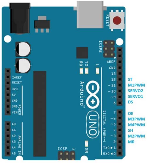
Here
- ST, DS, OE, SH, and MR is used for driving S hift Register
- M1PWM, M2PWM, M3PWM, and M4PWM are used for controlling DC motor speed. If DC motor speed controlling is not necessary make these pins HIGH.
- SERVO1 and SERVO2 for Servo Motors.
With this shield, making motor based projects are super easy with Arduino. You just have to fix the shield over Arduino and control motors using this shield. You can use the given code (in the end) or use your own code for controlling the motors according to your application.
You can also learn interfacing of all these motors and shift register with Arduino in our previous articles without using the Motor Driver shield:
- Interfacing Stepper Motor with Arduino UNO
- Controlling Multiple Servo Motor with Arduino
- DC Motor Control using Arduino
- How to Use Shift Register 74HC595 with Arduino Uno
Circuit and PCB Design using EasyEDA
To design this Arduino Motor Driver Shield, we have chosen the online EDA tool called EasyEDA. I have previously used EasyEDA many times and found it a great online tool to use since it has a large collection of footprints and it is open-source. After designing the PCB we can order the PCB samples by their low cost PCB fabrication services. Moreover, they also offer component sourcing service where they have a large stock of electronic components and users can order the required components along with the PCB boards.
While designing your circuits and PCBs with EasyEDA, you can make your circuit and PCB designs public so that other users can copy or edit them and can take benefit from your work, we have made the Circuit and PCB layout public for this project, available at the below link:
https://easyeda.com/circuitdigest/Motor-Driver-Sheild
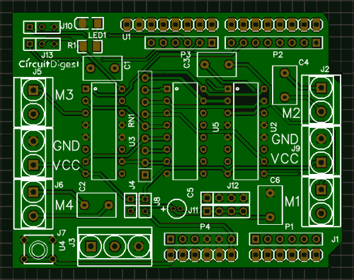
You can view any Layer (Top, Bottom, Topsilk, bottomsilk etc) of the PCB by selecting the layer form the ‘Layers’ Window. You can also view the PCB, how it will look after fabrication using the Photo View button in EasyEDA:
Calculating and Ordering Samples online
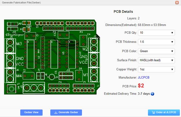
After completing the design of this Arduino Motor Shield, you can order the PCB through JLCPCB.com. To order the PCB from JLCPCB, you need Gerber File. To download Gerber files of your PCB just click the Fabrication Output button in EasyEDA editor page, then download from the EasyEDA PCB order page.
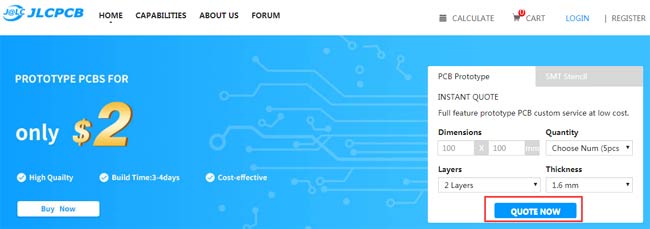
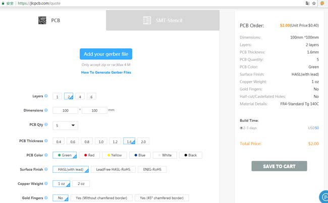
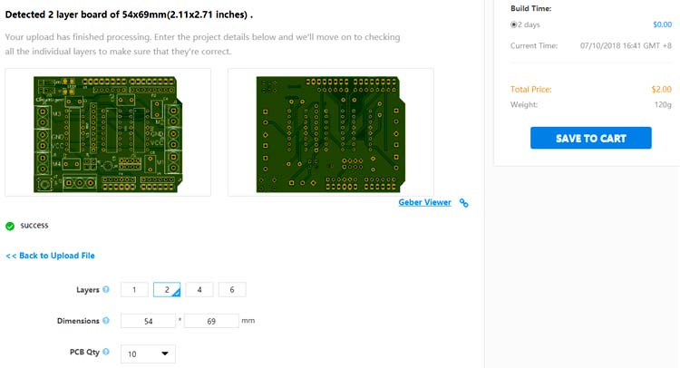
Now go to JLCPCB.com and click on Quote Now or Buy Now button, then you can select the number of PCBs you want to order, how many copper layers you need, the PCB thickness, copper weight, and even the PCB color, like the snapshot shown below:
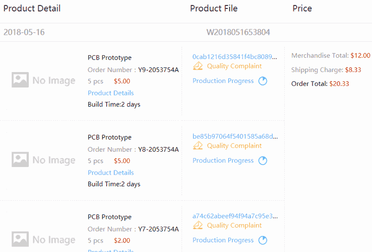
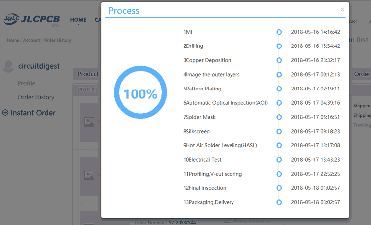
After ordering the PCB, you can check the Production Progress of your PCB with date and time. You check it by going on Account page and click on "Production Progress" link under the PCB like, shown in below image.
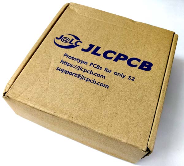
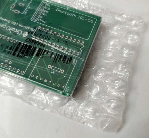
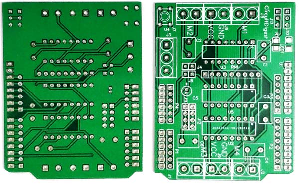
After few days of ordering PCB’s I got the PCB samples in nice packaging as shown in below pictures.
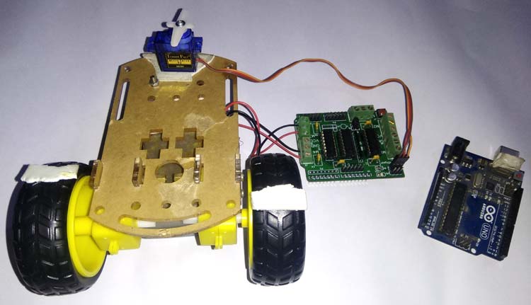
After getting these pieces I have mounted all the required components over the PCB connected it with Arduino for demonstration.
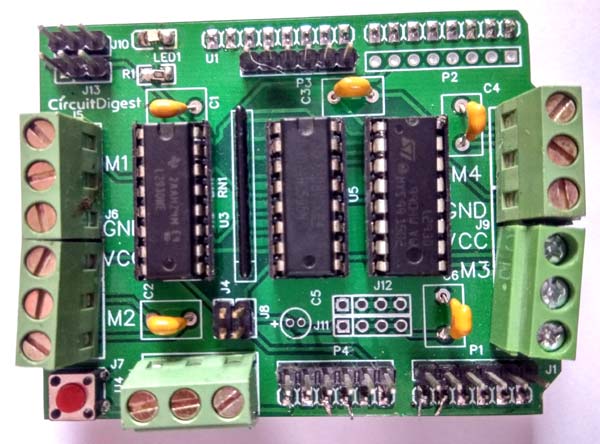
So our Arduino Motor Driver Shield is ready, and you can directly use it with Arduino to control many motors at a time.
Complete Project Code
#include <Servo.h>

Servo myservo;
#define MR 2

#define M2PWM 3

#define SH 4

#define M4PWM 5

#define M3PWM 6

#define OE 7

#define DS 8

#define SERVO1 9

#define SERVO2 10

#define M1PWM 11

#define ST 12
#define M1 0

#define M2 2

#define M3 4

#define M4 6
#define STOP 0

#define CW 1

#define CCW 2

char pAction=0x00;
void setup()

{

  Serial.begin(9600);

  pinMode(MR, OUTPUT);

  pinMode(M2PWM, OUTPUT);

  pinMode(SH, OUTPUT);

  pinMode(M4PWM, OUTPUT);

  pinMode(M3PWM, OUTPUT);

  pinMode(OE, OUTPUT);

  pinMode(DS, OUTPUT);

  pinMode(M1PWM, OUTPUT);

  pinMode(ST, OUTPUT);
  digitalWrite(M1PWM, HIGH);

  digitalWrite(M2PWM, HIGH);

  digitalWrite(M3PWM, HIGH);

  digitalWrite(M4PWM, HIGH);
  digitalWrite(MR, HIGH);

  digitalWrite(OE, LOW);
  myservo.attach(SERVO1);

  myservo.write(0);
}
void loop()

{
  DriveMotor(M1,CW);

  DriveMotor(M2,CCW);

  DriveMotor(M2,CW);

  DriveMotor(M3,CW);

  DriveMotor(M4,CW);

  myservo.write(0);

  delay(5000);

  DriveMotor(M1,STOP);

  DriveMotor(M2,STOP);

  DriveMotor(M3,STOP);

  DriveMotor(M4,STOP);

  delay(1000);

  DriveMotor(M1,CCW);

  DriveMotor(M2,CCW);

  DriveMotor(M3,CCW);

  DriveMotor(M4,CCW);

  myservo.write(90);

  delay(5000);

      DriveMotor(M1,STOP);

  DriveMotor(M2,STOP);

  DriveMotor(M3,STOP);

  DriveMotor(M4,STOP);

  delay(1000);

  DriveMotor(M1,CW);

  DriveMotor(M2,CCW);

  DriveMotor(M3,CW);

  DriveMotor(M4,CCW);

  myservo.write(180);

  delay(5000);

      DriveMotor(M1,STOP);

  DriveMotor(M2,STOP);

  DriveMotor(M3,STOP);

  DriveMotor(M4,STOP);

  delay(1000);

  DriveMotor(M1,CCW);

  DriveMotor(M2,CW);

  DriveMotor(M3,CCW);

  DriveMotor(M4,CW);

  myservo.write(90);

  delay(5000);

      DriveMotor(M1,STOP);

  DriveMotor(M2,STOP);

  DriveMotor(M3,STOP);

  DriveMotor(M4,STOP);

  delay(1000);

  DriveMotor(M1,STOP);

  DriveMotor(M2,CW);

  DriveMotor(M3,CCW);

  DriveMotor(M4,CW);

  myservo.write(0);

  delay(5000);

      DriveMotor(M1,STOP);

  DriveMotor(M2,STOP);

  DriveMotor(M3,STOP);

  DriveMotor(M4,STOP);

  delay(1000);

  DriveMotor(M1,STOP);

  DriveMotor(M2,STOP);

  DriveMotor(M3,CW);

  DriveMotor(M4,CCW);

  myservo.write(90);

  delay(5000);

    DriveMotor(M1,STOP);

  DriveMotor(M2,STOP);

  DriveMotor(M3,STOP);

  DriveMotor(M4,STOP);

  delay(1000);

  DriveMotor(M1,STOP);

  DriveMotor(M2,STOP);

  DriveMotor(M3,STOP);

  DriveMotor(M4,CCW);

  myservo.write(180);

  delay(5000);

  DriveMotor(M1,STOP);

  DriveMotor(M2,STOP);

  DriveMotor(M3,STOP);

  DriveMotor(M4,STOP);

  myservo.write(90);

  delay(5000);

}
int Action=0;

void DriveMotor(int Motor, int Dir)

{

  //  Serial.print("Motor :");

  //  Serial.println(Motor, HEX);

  //  Serial.print("Action:");

  //  Serial.println(Action,HEX);

    if(Dir == CW)

    {

      Action|=(1<<Motor);

      Action&=~(1<<Motor+1);

    }

    else if(Dir == CCW)

    {

      Action&=~(1<<Motor);

      Action|=(1<<Motor+1);

    }
    else

    {

            Action&=~(1<<Motor);

            Action&=~(1<<Motor+1);

    }

    Serial.print("Action:");

    Serial.println(Action, HEX);
   // delay(2000);


  for (int i = 0; i < 8; i++)

  {

    if ((Action << i) & 0x80)

      digitalWrite(DS, HIGH);

    else

      digitalWrite(DS, LOW);

    digitalWrite(SH, HIGH);

    delay(1);

    digitalWrite(SH, LOW);

  }

  digitalWrite(ST, HIGH);

  delay(1);

  digitalWrite(ST, LOW);

  pAction=Action;

}
Comments
Hello @Saddam,
Thank your for the project. I am following this myself and was able to put this together with exception of the capacitors. I you did not identify the polarity for mounting the capictors or the LED. I am assuming these are significant and required for ensuring that things work correctly. Would you be willing to clarify?
Thanks,
Kevin
Ceramic capacitors have no polarity, so that was news to me...glad I did the research and figured that out. I had my LED polarity wrong. Re-soldered that in the write direction based on looking at EasyEDA. If I was making this again I would edit the screen print for the LED with a + just to make it easier. Only other item to reference for others doing this project is that the through hole pins from the terminal blocks can rest on the USB and power components on the UNO. Trim those pins before you solder and it will be a lot cleaner and will fit the first time you connect your board with the UNO.

Yes as I see in posted. I need it to DIY for my own.