

In this tutorial, we are going to design an Arduino Uno based Robotic Arm from some cardboards and servo motors. Entire process of construction has been explained in detail below. Here in this project Arduino Uno is programmed to control servo motors which are serving as joints of Robotic arm. This setup also looks as a Robotic Crane or we can convert it into a Crane by doing some easy tweaks. This project will be helpful for beginners who want to learn to develop a Simple Robot in low cost or just want to learn working with Arduino and servo motors.
This Arduino Robotic Arm can be controlled by four Potentiometer attached to it, each potentiometer is used to control each servo. You can move these servos by rotating the pots to pick some object, with some practice you can easily pick and move the object from one place to another. We have used low torque servos here but you can use more powerful servos to pick heavy objects. The whole process has been well demonstrated in the Video at the end. Also check our other Robotics Projects here.
Components Required
- Arduino Uno
- 1000uF Capacitor (4 pieces)
- 100nF Capacitor (4 pieces)
- Servo Motor (SG 90- four pieces)
- 10K pot- Variable Resistor (4 pieces)
- Power Supply (5v- preferably two)
Servo Motor
First we talk a bit about Servo Motors. Servo Motors are mainly used when there is a need for accurate shaft movement or position. These are not proposed for high speed applications. Servo motors are proposed for low speed, medium torque and accurate position application. So these motors are best for designing robotic arm.
Servo motors are available at different shapes and sizes. We are going to use small servo motors, here we use four SG90 servos. A servo motor will have mainly there wires, one is for positive voltage another is for ground and last one is for position setting. The RED wire is connected to power, Black wire is connected to ground and YELLOW wire is connected to signal. Go through this tutorial of Controlling Servo Motor using Arduino or how to control servo with arduino to learn more about it. In Arduino we have predefined libraries to control the Servo, so it is very easy to control servo, which you will learn along with this tutorial.
Construction of Robotic Arm
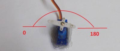
Take a flat and stable surface, like a table or a hard card board. Next place a servo motor in the middle and glue it in place. Make sure the degree of rotation is in the area presented in figure. This servo acts as base of arm.
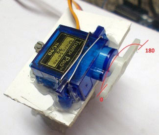
Place a small piece of cardboard on top of first servo and then place the second servo on this piece of board and glue it in place. The servo rotation must match the diagram.
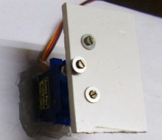
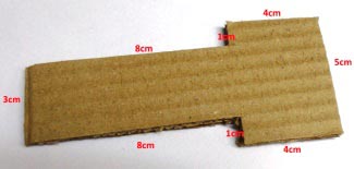
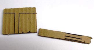
Take some cardboards and cut them into 3cm x 11cm pieces. Make sure the piece is not softened. Cut a rectangular hole at one end (leave 0.8cm from bottom) just enough to fit another servo and at another end fit the servo gear tightly with screws or by glue. Then fit the third servo in the first hole.
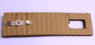
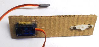
Now cut another cardboard piece with lengths shown in figure below and glue another gear at the bottom of this piece.
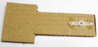
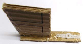
Now glue the fourth and last servo at the edge of second piece as shown in figure.
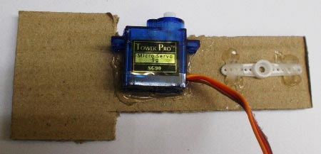
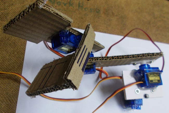
With this, two pieces together looks like.
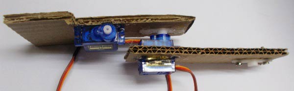
When we attach this setup to the base it should look like,
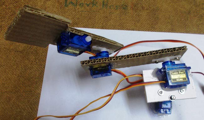
It’s almost done. We just need to make the hook to grab and pick the object like a robotic hand. For hook, cut another two pieces of card board of lengths 1cmx7cm & 4cmx5cm. Glue them together as shown in figure and stick final gear at the very edge.
Mount this piece on top and with this we have done building our Robotic Arm.
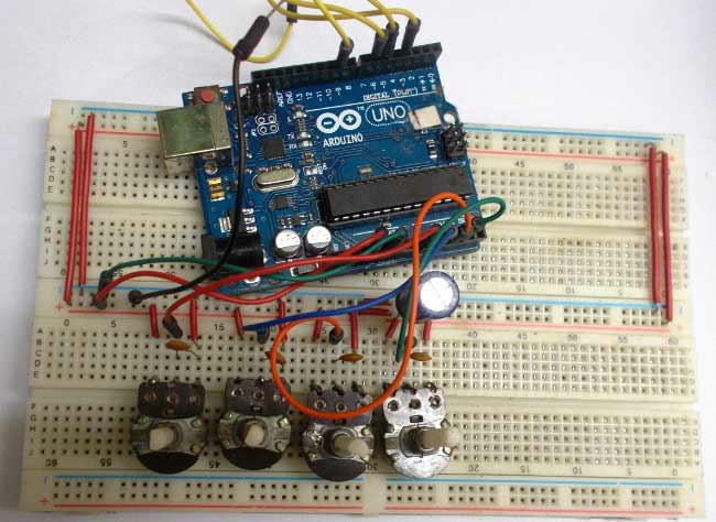
With this, our basic robotic arm design got completed and that's how we have built our low cost robotic arm. Now connect the circuit in breadboard as per circuit diagram.
Circuit Diagram and Working Explanation:
The circuit connection for Arduino Uno Robotic Arm is shown below.

The voltage across variable resistors is not completely linear; it will be a noisy one. So to filter out this noise, capacitors are placed across each resistor as shown in figure.
Now we will feed the voltage provided by these variable resistor (voltage which represents position control) into ADC channels of Arduino. We are going to use four ADC channels of UNO from A0 to A3 for this. After the ADC initialization, we will have digital value of pots representing the position needed by user. We will take this value and match it with servo position.
Arduino has six ADC channels. We have used four for our Robotic Arm. The UNO ADC is of 10 bit resolution so the integer values ranging from 0-1023 (2^10=1024 values). This means that it will map input voltages between 0 and 5 volts into integer values between 0 and 1023. So for every (5/1024= 4.9mV) per unit. Learn more about mapping the voltage levels using ADC channels in Arduino here.
Now, for the UNO to convert analog signal into digital signal, we need to Use ADC Channel of Arduino Uno, with the help of below functions:
1. analogRead(pin);
2. analogReference();
3. analogReadResolution(bits);
Arduino ADC channels have a default reference value of 5V. This means we can give a maximum input voltage of 5V for ADC conversion at any input channel. Since some sensors provide voltages from 0-2.5V, so with a 5V reference, we get lesser accuracy, so we have an instruction that enables us to change this reference value. So for changing the reference value we have “analogReference();”
As default we get the maximum board ADC resolution which is 10bits, this resolution can be changed by using instruction (“analogReadResolution(bits);”).
In our Robotic hand circuit, we have left this reference voltage to the default, so we can read value from ADC channel by directly calling function “analogRead(pin);”, here “pin” represents pin where we connected the analog signal, say we want to read “A0”. The value from ADC can be stored into an integer as int SENSORVALUE0 = analogRead(A0);.
Now let’s talk about the SERVO, the Arduino Uno has a feature which enables us to control the servo position by just giving the degree value. Say if we want the servo to be at 30, we can directly represent the value in the program. The SERVO header (Servo.h) file takes care of all the duty ratio calculations internally.
#include <Servo.h>
servo servo0;
servo0.attach(3);
servo0.write(degrees);
Here first statement represents the header file for controlling the SERVO MOTOR. Second statement is naming the servo; we leave it as servo0 as we are going to use four. Third statement states where the servo signal pin is connected; this must be a PWM pin. Here we are using PIN3 for first servo. Fourth statement gives commands for positioning servo motor in degrees. If it is given 30, the servo motor rotates 30 degrees.
Now, we have SG90 servo position from 0 to 180 and the ADC values are from 0-1023. We will use a special function which matches both values automatically.
sensorvalue0 = map(sensorvalue0, 0, 1023, 0, 180);
This statement maps both values automatically and stores the result in integer ‘servovalue0’.
This is how we have controlled the Servos in our Robotic Arm project using Arduino. Check the full code below.
How to Operate Robotic Arm:
There are four pots provided to the user. And by rotating these four pots, we provide variable voltage at the ADC channels of UNO. So the digital values of Arduino are under control of user. These digital values are mapped to adjust the servo motor position, hence the servo position is in control of user and by rotating these Pots user can move the joints of Robotic arm and can pick or grab any object.
Complete Project Code
#include <Servo.h>
Servo servo0;
Servo servo1;
Servo servo2;
Servo servo3;
int sensorvalue0;
int sensorvalue1;
int sensorvalue2;
int sensorvalue3;
void setup()
{
  pinMode(A0,INPUT);
  pinMode(3,OUTPUT);
  servo0.attach(3);

  pinMode(A1,INPUT);
  pinMode(5,OUTPUT);
  servo1.attach(5);

  pinMode(A2,INPUT);
  pinMode(6,OUTPUT);
  servo2.attach(6);

  pinMode(A3,INPUT);
  pinMode(9,OUTPUT);
  servo3.attach(9);
}
void loop()
{
  sensorvalue0 = analogRead(A0);
  sensorvalue0 = map(sensorvalue0, 0, 1023, 0, 180);
  servo0.write(sensorvalue0);
  sensorvalue1 = analogRead(A1);
  sensorvalue1 = map(sensorvalue1, 0, 1023, 0, 180);
  servo1.write(sensorvalue1);
  sensorvalue2 = analogRead(A2);
  sensorvalue2 = map(sensorvalue2, 0, 1023, 0, 180);
  servo2.write(sensorvalue2);
  sensorvalue3 = analogRead(A3);
  sensorvalue3 = map(sensorvalue3, 0, 1023, 0, 180);
  servo3.write(sensorvalue3);
}
Comments
Nice effort Dilip
monib ahmad you can use flex sensors , lm 324, and rf module to control it by your hand wirelessly
There are lot of techniques out there, check these projects and get some idea to control it from hand movement: Hand Gesture Controlled Robot using Arduino and DIY Arduino Robotic Hand
I want to do same thing wirelessly using 4 potentiometer....and NRF24L01 and 4 servoos......can you help me with code......for Arduino...one both side
Which book best for preparing project by using arduino,microcontroller, which help me make to project by my hand!!!
Which software is used to write the code?
Arduino Uno IDE, check this link https://www.arduino.cc/en/Main/Software
Amazing job Dilip. I myself am going to make something similar soon with a bit of a twist on how to control the robotic arm (use something else instead of the 10k pots). Great tutorial!
if you used basa wood and extended the arm would you use stronger servos
It would depend on how far you would be extending the arm. The main thing that each servo has to provide torque for is to counteract the moment caused by the motor on the end of the arm which it is moving. The actual arm itself will have a very negligible effect on the moment here because it is on such a small scale. Also considering that Balsar wood and Cardboard are quite similiar in mass this again probably wouldn't be a problem. However balsar wood is very brittle so may snap in have due to the servos on the end of them anyway!
Will this project work
nice work , i really liked the idea
how can i make it repeat the work alone without the interfare of the pots...
or i just mean i would like to give it some actions to do and it repeats those actions by it self with some kind of delay
is the code perfect and do i have to supply the power to arduino via pc?
the wholw setup of project is very nice I have tried and maid it sucsessfully by makaing some modification very good job
up to what weight can it approximately lift?
Is it possible to use a analog outputs from a PLC rather than the four Potentiometer and if so would I have to change anything in the code?
can you give code to control servo motors without using potentiometer?
The same is done in this tutorial and the complete code is also given above
how to connect the circuit on breadboard ..can u just send me the video to my mail...and making of the arm also...
what is the voltage range required for the capacitors
1000uF Capacitor (4 pieces)
100nF Capacitor (4 pieces)
?
I am working on this project but my servo are vibrating contiously, please tell me how to fix it.
CAN I USE THE VERY SAME COMPONENTS BUT THEN SUBSTITUTE THE MOTORS BY ANOTHER TYPES OF MOTORS, YET STILL THE SRVOMOTORS.
Just make sure the motors dont consume more power. Suppose if they do make sure you power supply could source it. If checked you are good to go
Can the same project be done with a joystick rather than potentiometers
Can u plz tell me how to simulate the above circuit
Hi, is it possible to code a pick-and-place robotic arm that does the process independently of other control inputs (such as pots, joysticks etc). i.e. picks an object, detects whether the object is metal/non-metal, and sorts it by placing it at different angle displacements? That is, without human intervention via pots etc.?
How to make all this system wireless if u have any solution please contact me on my gmail.
the circuit diagram given above is wrong. Their are some modifications in! It dosent match as shown in the video fully!!
There in no correction in circuit diagram. you may confused because in circuit diagram there is no vcc & ground connection in arduino uno. In simulation we can't give power and ground connection to arduino uno.
Hi, can someone please help me? I understand that we have to use two 5V power supplies but where do I connect it? To the Arduino?

will u plz guide me that how we can perform the same operation by the movement of our own hand.......