

If you are interested in building robots, then it is certain that you need to learn how to control the speed and direction of a DC motor, and in one of our previous tutorials, we did just that using the popular L293D Motor Driver IC and ESP32. However, there is a different IC called DRV8833, which is also a dual drive motor driver solution and is cheaper than the L293D IC. So in this project, we will be interfacing the DRV8833 Arduino, while we will also know everything about this DRV8833 module. Here we used Arduino Pro Mini; however, any Arduino model can be used to build this drv8833 arduino project.
DRV8833 Dual Motor Driver with Arduino - Quick Overview
Build Time: 2-4 hours | Cost: $15-30 | Difficulty: Beginner-Intermediate
What You'll Learn: PWM speed control, H-bridge direction control, Arduino motor interfacing, Basic schematic wiring
Applications: Robot locomotion, DC motor projects, Stepper motor driving, Solenoid/relay control
Table of Contents
Controlling DC Motors with Microcontrollers
To get complete control of the motor, we need to take control of the speed and direction of the motor, and to do that, we need to use Pulse Width Modulation or PWM Technique to control the speed, and we are going to use the internal H-bridge to control the direction of the motor. We previously did a basic DC motor control using Arduino and the PWM technique.
PWM - Motor Speed Control
When we are talking about a DC motor, to change the speed of the DC motor, we need to change the amplitude of the input voltage that is applied to the motor. A common technique to do that is PWM (Pulse Width Modulation). In PWM, the applied voltage is adjusted by sending a series of pulses, so the output voltage is proportional pulse width generated by the microcontroller, which is also known as the duty cycle. We have explained Pulse width modulation in detail earlier. Also, check more PWM based projects with other microcontrollers by following the link.
The higher the duty cycle, the higher the average voltage applied to the DC motor (resulting in higher speed) and the shorter the duty cycle, the lower the average voltage applied to the DC motor (resulting in lower speed).
H-Bridge Motor Direction Control
To change the direction of rotation of a DC motor, you need to change the polarity of the supply. A common technique to do that is by using an H-bridge motor driver. An H-bridge motor driver consists of four switches (usually MOSFETs) arranged in a certain formation, and the motor is connected to the centre of the arrangement to form the H-like structure.
By closing/enabling two opposite switches, we can change the direction of the flowing current, thus changing the direction of rotation.
DRV8833 Motor Driver IC Overview
The DRV8833 motor driver IC is a dual-channel motor drive IC capable of driving two bidirectional motors or a single stepper motor. The output driver block of each H-bridge consists of N-channel power MOSFETs configured as an H-bridge to drive the motor windings. Each H-bridge includes circuitry to regulate or limit the winding current. This DRV8833 dual motor driver is also designed to drive inductive loads such as relays, solenoids, DC, and bipolar stepping motors.
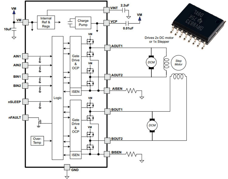
The internal structure of the DRV8833 motor driver IC is shown above, and it's taken from the DRV8833 dataset of the device. The device integrates two NMOS H-bridges and current regulation circuitry. The DRV8833 module can be powered with a supply voltage from 2.7 to 10.8 V and can provide an output current up to 1.5-A RMS. The device also includes a low-power sleep mode, which lets the system save power when not driving the motor.
DRV8833 Module Pinout and Wiring Diagram
The DRV8833 pinout of the DRV8833 motor driver module is shown below. The DRV8833 module has a total of 12 pins that can be connected to the microcontroller and motor for complete drv8833 arduino interfacing.
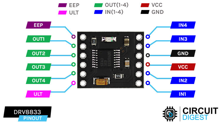
Drv8833 Motor Driver Pinout Details
EEP, this is the sleep pin for the DRV8833 motor driver module. Logic high to enable the device, logic low to enter low-power sleep mode and reset all
OUT(1-2) Output1 and Output2 of the internal H-Bridge A.
OUT(3-4) Output1 and Output2 of the internal H-Bridge B.
IN(1-2) Input1 and Input2 of the internal H-Bridge A for drv8833 arduino control signals
IN(3-4) Input3 and Input4 of the internal H-Bridge B for DRV8833 motor driver Arduino control signals
ULT Fault pin of the IC. Logic low when in fault condition (overtemperature, overcurrent)
VCC Supply pin of the IC. Max Operating Voltage: 11.8V for for drv8833 module.
GND Ground pin of the IC connects it to the supply Ground.
DRV8833 Motor Driver IC Module Parts
The parts marking of the DRV8833 module is shown below. The module is made with generic components, and in this action, it is shown below.
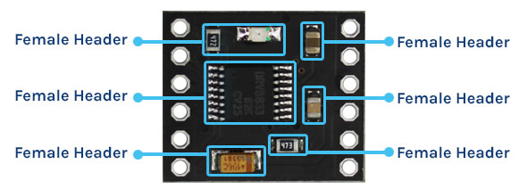
As you can see in the image above, in the middle of the module, we have our DRV8833 IC, and there are mainly three bypass capacitors on the board: a 10uF tantalum capacitor for input power. A 2.2uF capacitor for the VINT Pin and a 0.1uF capacitor for the VCP Pin. Finally, we have the onboard power indicator with its 4.7K Current limiting resistor.
Schematic Diagram of the DRB8833 Module
The internal schematic diagram of the DRV8833 module is shown below. The circuit diagram of the module is very simple, as it has very few components on the PCB.

As you can see in the schematic diagram, the connection for all the bypass capacitors to the IC is shown. We have also shown the connection for the pin header, and beside the header, you can see the names of the pins in the PCB. On the PCB, there is also an LED with a current-limiting resistor as an indicator.
Commonly Asked Questions about DRV8833 Motor Driver IC
⇥ What is the difference between L293D and DRV8833?
The L293D and the DRV8833 are both motor driver ICs, but they have differences. Both the ICs have a maximum current of 1.5A, but the operating voltage of the DRV8833 IC is 11.8V, whereas the operating voltage of the L293D is 40V.
⇥ Can I run the stepper motor with DRV8833?
Yes, the DRV8833 IC can drive stepper motors. But micro-stepping is not possible with this IC; for that, you will need a dedicated driver IC.
⇥ Can I connect 4 motors to DRV8833?
The DRV8833 is designed to drive two DC motors. If you want to drive 4 motors, it may still be feasible if you sacrifice direction control.
⇥ What is the DRV8833 motor driver used for?
It is the DRV8833 motor driver IC intended for use with DC motors and stepper motors with Arduino or some other microcontroller. The DRV8833 allows control of motors in either direction with PWM speed control up to 1.5 Amp RMS current and a voltage supply range from 2.7V to 10.8V.
⇥ How do you wire the DRV8833 with Arduino?
Connect the IN1 to IN4 pins of DRV8833 to Arduino digital pins (9, 6, 5, 3), VCC to the 5V supply, GND to ground, and the motor terminals to the OUT1-OUT4 pins. The wiring diagram shows the enable pin (EEP) tied high for the driver module, which is a must in most cases.
⇥ So, what are some distinctions between the DRV8833 and L293D?
The main differences between DRV8833 and L293D are, the DRV8833 uses a MOSFET H-bridge design, whereas L293D uses bipolar transistors. Low-drop-out MOSFET means less heat is dissipated with lower voltage drop when using the L293D DC motor drive. And as a matter of fact, DRV8833 provides current sensing and regulation. However, if you need to control higher voltage (and higher power) applications that require the higher-rated voltage (36 V vs. 10.8 V typically advertised with the DRV8833), it is not as fast acting and more prefer L293D.
Simple Circuit Diagram: DRV8833 Interfacing with Arduino
The schematic diagram of the DRV8833 Module interfacing with Arduino is shown below.

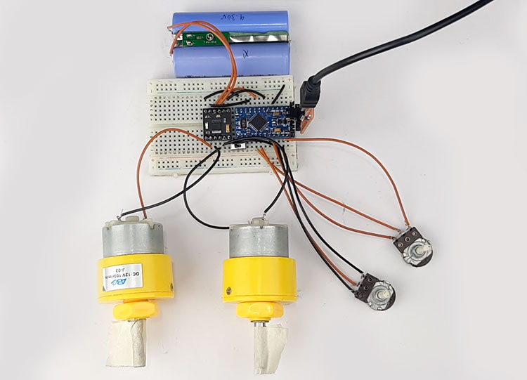
The DRV8833 motor driver wiring diagram shows the DRV8833 Arduino interfacing to the Arduino Pro Mini. As shown in the diagram, pins 9,6,5,3 are connected to the IN1, IN2, IN3, and IN4 pins of the DRV8833 module, respectively, and the output pins are connected to the two motors. A switch is connected to pin 10 of the Arduino Pro Mini, and this switch is used to change the direction of rotation. There are two potentiometers to adjust the speed of the motors. The circuit is powered by an 8.4V battery. Lastly, there is a switch to control the direction of the motors. The Hardware setup of the DRV8833 module is shown below.
DRV8833 Overheating Solutions
If your DRV8833 module is getting excessively hot during operation, implement these solutions:
Problem | Cause | Solution |
|---|---|---|
IC very hot | High current draw | Add heatsink, reduce motor load |
Thermal shutdown | Overcurrent condition | Check motor stall, add current limiting |
Erratic operation | Power supply voltage drop | Use larger capacity battery/supply |
Motor stuttering | EMI from motors | Add 0.1μF capacitors across motor terminals |
Arduino Code for Interfacing the DRV8833 Motor Driver IC with Arduino
Complete code for Arduino DC motor speed control using PWM is given below. Here, we are explaining the code in detail.
Now that we have a clear understanding of how the DRV8833 Module works, we can write some code to control the speed and direction of the motor.
We start our code by defining all the pins for the motor driver and the switches.
#define mode_pin  10
#define IN1_PIN 9
#define IN4_PIN 6
#define IN3_PIN 5
#define IN4_PIN 3
Next, we have our setup function. In the setup function, we make the PWM pins as outputs and the switch pins as inputs, and we set all the pins low.
void setup() {
  pinMode(IN1_PIN, OUTPUT);
  pinMode(IN4_PIN, OUTPUT);
  pinMode(IN3_PIN, OUTPUT);
  pinMode(IN4_PIN, OUTPUT);
  pinMode(mode_pin, INPUT);
  digitalWrite(IN1_PIN, LOW);
  digitalWrite(IN4_PIN, LOW);
  digitalWrite(IN3_PIN, LOW);
  digitalWrite(IN4_PIN, LOW);
}
Next, we have our loop function. In the loop function, we check the switch position. If the switch is in the high state, we rotate the motor clockwise, and if the state of switch is low we rotate the motor counterclockwise.
void loop() {
  int sensorValue = analogRead(A0);
  int sensorValue1 = analogRead(A1);
  if (digitalRead(mode_pin) == LOW) {
    digitalWrite(IN3_PIN, LOW);
    analogWrite(IN4_PIN, sensorValue);
    digitalWrite(IN1_PIN, LOW);
    analogWrite(IN4_PIN, sensorValue1);
  }
  if (digitalRead(mode_pin) == HIGH) {
    digitalWrite(IN4_PIN, LOW);
    analogWrite(IN3_PIN, sensorValue);
    digitalWrite(IN4_PIN, LOW);
    analogWrite(IN1_PIN, sensorValue1);
  }
}
We also use the analogRead() and analogWrite() functions to read the ADC value and write that value as a PWM signal.
DRV8833 vs L293D Technical Comparison
Specification | DRV8833 Motor Driver | L293D Motor Driver |
|---|---|---|
Supply Voltage Range | 2.7V to 10.8V | 4.5V to 36V |
Continuous Current per Channel | 1.5A RMS | 600mA |
Peak Current | 2A | 1.2A |
Voltage Drop (Typical) | 0.3V @ 1A | 2.0V @ 1A |
H-Bridge Technology | N-Channel MOSFET | Bipolar Transistor |
Current Regulation | Built-in | External Required |
PWM Frequency | Up to 250kHz | Up to 5kHz |
Technical Summary and Github Repository
The technical summary covers all the essentials; a hardware design project and logic for programming are briefly described. Uses shall include reference documentation for enthusiasts to get an understanding of how the project works. The GitHub Repository has the complete source code, schematics, and documentation that would give you everything needed to reproduce and customise the project.


Projects Using Motor Driver IC and Arduino

DIY Raspberry Pi Motor Driver HAT
Looking for a cool little Raspberry Pi project online? Then search no more because in this project, we have built a Raspberry Pi-based motor drive hat that can be used to drive any motor that consumes 1.5A peak current.

Android Controlled Robot using 8051 Microcontroller
Looking for a 8051-based motor controller which is easy to use and simple to make, and costs less than any other microcontroller-based solution, then you can check this project out, because in this project, we have interfaced a 8051 microcontroller to build a PWM-based motor driver system.

Mobile Phone Controlled Robot Car using G-Sensor and Arduino
If you are looking to build a robot car, then this project is for you, because in this project, we have built an Android phone and used it to drive a robot.

DIY Brushless Motor Using Fidget Spinner
If you are looking for some interesting projects online, then this project is for you, because in this project, we have used a BLDC motor to make a fidget spinner that can be used to understand how it works and how to interact with it.
Complete Project Code
#define mode_pin  10
#define IN1_PIN 9
#define IN4_PIN 6
#define IN3_PIN 5
#define IN4_PIN 3
void setup() {
  pinMode(IN1_PIN, OUTPUT);
  pinMode(IN4_PIN, OUTPUT);
  pinMode(IN3_PIN, OUTPUT);
  pinMode(IN4_PIN, OUTPUT);
  pinMode(mode_pin, INPUT);
  digitalWrite(IN1_PIN, LOW);
  digitalWrite(IN4_PIN, LOW);
  digitalWrite(IN3_PIN, LOW);
  digitalWrite(IN4_PIN, LOW);
}
void loop() {
  int sensorValue = analogRead(A0);
  int sensorValue1 = analogRead(A1);
  if (digitalRead(mode_pin) == LOW)
  {
    digitalWrite(IN3_PIN, LOW);
    analogWrite(IN4_PIN, sensorValue);
    digitalWrite(IN1_PIN, LOW);
    analogWrite(IN4_PIN, sensorValue1);
  }
  if (digitalRead(mode_pin) == HIGH)
  {
    digitalWrite(IN4_PIN, LOW);
    analogWrite(IN3_PIN, sensorValue);
    digitalWrite(IN4_PIN, LOW);
    analogWrite(IN1_PIN, sensorValue1);
  }
}
Comments
Hi,
I've yet to see how the DRV8833 can be used to control a Nema 17HS4023 stepper. I can't find an example anywhere, does this mean it doesn't work for steppers ?

Hello I was wanting to see if you could help me out I was using your code it's working alright but for some reason when I start turning the potentiometer about the 15% mark there is a small spot where it just stops moving it just stands still then when I continue it starts going again and then there is another spot about the halfway mark where it also does it again and then it just continues going again and then just continues until the end if you could help me out i would really appreciate it