

Inverters, Converters, SMPS circuits and Speed controllers.... One thing that is common in all these circuits is that it consists of many electronic switches inside it. These switches are nothing but Power electronic devices like MOSFET, IGBT, TRIAC etc. In order to control such power electronic switches we commonly use something called PWM signals (Pulse Width Modulation). Apart from this, PWM signals are also used for driving Servo motors and also for other simple tasks like controlling the brightness of a LED.
In our previous article we learnt about ADC, while ADC is used to read Analog signals by a digital device like microcontroller. A PWM can be considered as an exact opposite of it, PWM is used to produce Analog signals from a digital device like microcontroller. In this article we will learn about what is PWM, PWM signals and some parameters associated with it, so that we will be confident in using them in our designs.
What is PWM (Pulse Width Modulation)?
PWM stands for Pulse Width Modulation; we will get into the reason for such a name later. But, for now understand PWM as a type of signal which can be produced from a digital IC such as microcontroller or 555 timer. The signal thus produced will have a train of pulses and these pulses will be in form of a square wave. That is, at any given instance of time the wave will either be high or will be low. For the ease of understanding let us consider a 5V PWM signal, in this case the PWM signal will either be 5V (high) or at ground level 0V (low). The duration at which the signals stays high is called the “on time” and the duration at which the signal stays low is called as the “off time”.
For a PWM signal we need to look at two important parameters associated with it one is the PWM duty cycle and the other is PWM frequency.
Duty cycle of the PWM
As told earlier, a PWM signal stays on for a particular time and then stays off for the rest of the period. What makes this PWM signal special and more useful is that we can set for how long it should stay on by controlling the duty cycle of the PWM signal.
The percentage of time in which the PWM signal remains HIGH (on time) is called as duty cycle. If the signal is always ON it is in 100% duty cycle and if it is always off it is 0% duty cycle. The formulae to calculate the duty cycle is shown below.
Duty Cycle =Turn ON time/ (Turn ON time + Turn OFF time)
The following image represents a PWM signal with 50% duty cycle. As you can see, considering an entire time period (on time + off time) the PWM signal stays on only for 50% of the time period.
By controlling the Duty cycle from 0% to 100% we can control the “on time” of PWM signal and thus the width of signal. Since we can modulate the width of the pulse, it got its iconic name “Pulse width Modulation”.
Frequency of a PWM
The frequency of a PWM signal determines how fast a PWM completes one period. One Period is the complete ON and OFF time of a PWM signal as shown in the above figure. The formulae to calculate the Frequency is given below
Frequency = 1/Time Period
Time Period = On time + Off time
Normally the PWM signals generated by microcontroller will be around 500 Hz, such high frequencies will be used in high speed switching devices like inverters or converters. But not all applications require high frequency. For example to control a servo motor we need to produce PWM signals with 50Hz frequency, so the frequency of a PWM signal is also controllable by program for all microcontrollers.
Some commonly arising questions on PWM
What is the difference between the Duty cycle and Frequency of a PWM signal?
The duty cycle and frequency of a PWM signals are often confused upon. As we know a PWM signal is a square wave with a particular on time and off time. The sum of this on time and off time is called as one time period. The inverse of one time period is called frequency. While the amount of time the PWM signal should remain on in one time period is decide by Duty cycle of the PWM.
To put it simple, how fast the PWM signal should turn on and turn off is decided by the frequency of the PWM signal and in that speed how long the PWM signal should remain turned on is decided by the duty cycle of the PWM signal.
How to convert PWM signals into Analog Voltage?
For simple applications like controlling the speed of a DC motor or adjusting brightness of an LED we need to convert the PWM signals into analog voltage. This can be easily done by using a RC filter and is commonly used where a DAC feature is required. The circuit for the same is shown below
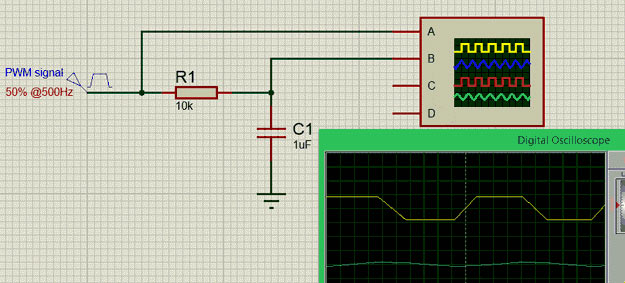
In the graph shown above, the Yellow coloured one is the PWM signal and the blue colour one is the output analog voltage. The value of the resistor R1 and capacitor C1 can be calculated based on the frequency of the PWM signal but normally a 5.7K or 10K resistor and a 0.1u or 1u Capacitor is used.
How to calculate the output voltage of PWM signal?
The output voltage of a PWM signal after converting it to analog will be the percentage of Duty cycle. For example if the operating voltage is 5V then the PWM signal will also have 5V when high. In such case for a 100% duty cycle the output voltage will be 5V for a 50% duty cycle it will be 2.5V.
Output Voltage = Duty cycle (%) * 5
Examples:
We have previously used PWM with various microcontroller in many of our projects:
- Pulse width Modulation with ATmega32
- PWM with Arduino Uno
- Generating PWM using PIC Microcontroller
- Raspberry Pi PWM Tutorial
- Servo Motor Control with Raspberry Pi
- Pulse width Modulation (PWM) using MSP430G2
- Pulse width Modulation (PWM) in STM32F103C8
- Servo Motor Control with Raspberry Pi
- DC Motor Control with Raspberry Pi
- 1 watt LED Dimmer
- Arduino Based LED Dimmer using PWM
Further check all the PWM related projects here.
