

The Analog world with digital Electronics
Few years back the entire electronics devices that we use today like phones, computers, Televisions etc were analog in nature. Then slowly the landline phones were replaced by modern mobile phones, CRT Televisions and monitors were replaced by LED displays, computers with vacuum tubes evolved to be more powerful with microprocessors and microcontrollers inside them and so on..
In today’s digital age we are all surrounded by the advanced digital electronic devices, this might deceive us to think that everything around us is digital in nature, which is not true. The world has always been analog in nature, for instance everything that we humans feel and experience like speed, temperature, air velocity, sunlight, sound etc are analog in nature. But our electronic devices which run on microcontrollers and microprocessors cannot read/interpret these analog values directly since they run only on 0’s and 1’s. So we need something which will convert all these analog values into 0’s and 1’s so that our microcontrollers and microprocessors can understand them. This something is called the Analog to Digital Converters or ADC for short. In this article we will learn everything about ADC and how to use them.
What is ADC and how to use it?
As said earlier ADC stands for Analog to digital conversion and it is used to convert analog values from real world into digital values like 1’s and 0’s. So what are these analog values? These are the ones that we see in our day to day life like temperature, speed, brightness etc. But wait!! Can an ADC convert temperature and speed directly into digital values like 0’s and 1’s?
No defiantly not. An ADC can only convert analog voltage values into digital values. So which ever parameter we wish to measure, it should be converted into voltage first, this conversion can be done with the help of sensors. For example to convert temperature values into voltage we can use a Thermistor similarly to convert brightness to voltage we can use a LDR. Once it is converted to voltage we can read it with the help of ADC’s.
In order to know how to use an ADC we should first get familiar with some basic terms like, channels resolution, range, reference voltage etc.
Resolution (bits) and channels in ADC
When you read the specification of any Microcontroller or ADC IC, the details of the ADC will be given using the terms channels and Resolution (bits). For instance an Arduino UNO’s ATmega328 has a 8-channel 10-bit ADC. Not every pin on a microcontroller can read Analog voltage, the term 8-channel means that there are 8 pins on this ATmega328 microcontroller which can read Analog voltage and each pin can read the voltage with a resolution of 10-bit. This will vary for different types of Microcontrollers.
Let us assume that our ADC range is from 0V to 5V and we have a 10-bit ADC this means our input voltage 0-5 Volts will be split into 1024 levels of discrete analog values(210 = 1024). Meaning 1024 is the resolution for a 10-bit ADC, similarly for a 8-bit ADC resolution will be 512 (28) and for a 16-bit ADC resolution will be 65,536 (216).
With this if the actual input voltage is 0V then the MCU’s ADC will read it as 0 and if it is 5V the MCU will read 1024 and if it somewhere in between like 2.5V then the MCU will read 512. We can use the below formulae to calculate the digital value that will be read by the MCU based on the Resolution of the ADC and Operating voltage.
(ADC Resolution / Operating Voltage) = (ADC Digital Value / Actual Voltage Value)
Reference Voltage for an ADC
Another important term that you should be familiar with is the reference voltage. During an ADC conversion the value of unknown voltage is found by comparing it with a known voltage, this is known voltage is called as Reference voltage. Normally all MCU has an option to set internal reference voltage, meaning you can set this voltage internally to some available value using software (program). In an Arduino UNO board the reference voltage is set to 5V by default internally, if required user can set this reference voltage externally through the Vref pin also after making the required changes in the software.
Always remember that the measured analog voltage value should always be less than the reference voltage value and the reference voltage value should always be less than the operating voltage value of the microcontroller.
Example
Here we are taking example of ADC which has 3 bit resolution and 2V reference voltage. So it can map the 0-2v analog voltage with 8 (23) different levels, like shown in the below picture:
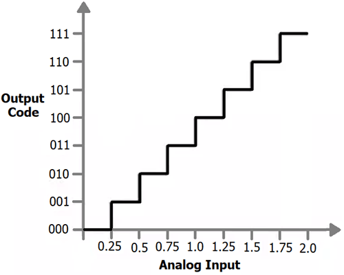
So if analog voltage is 0.25 then the digital value will be 1 in decimal and 001 in binary. Likewise if analog voltage is 0.5 then the digital value will be 2 in decimal and 010 in binary.
Some microcontroller has inbuilt ADC like Arduino, MSP430, PIC16F877A but some microcontroller don’t have it like 8051, Raspberry Pi etc and we have to use some external Analog to digital converter ICs like ADC0804, ADC0808.
Below you can find various examples of ADC with different microcontrollers:
- How to Use ADC in Arduino Uno?
- Raspberry Pi ADC Tutorial
- Interfacing ADC0808 with 8051 Microcontroller
- 0-25V Digital Voltmeter using AVR Microcontroller
- How to use ADC in STM32F103C8
- How to use ADC in MSP430G2
ADC types and working
There are many types of ADC, the most commonly used ones are Flash ADC, Dual Slope ADC, Successive approximation and Dual Slope ADC. To explain how each of these ADC’s work and the difference between them would be out of scope for this article as they are fairly complex. But to give a rough idea ADC has an internal capacitor which will get charged by the analog voltage that is to measured. Then we measure the voltage value by discharging the capacitor over a period of time.
Some commonly arising questions on ADC
How to measure more than 5V using my ADC?
As discussed earlier an ADC module cannot measure voltage value more than the operating voltage of the microcontroller. That is a 5V microcontroller can measure only a maximum of 5V with its ADC pin. If you want to measure anything more than that say, you want to measure 0-12V then you can map the 0-12V into 0-5V by using a potential divider or voltage divider circuit. This circuit will use a pair of resistors to map down the values for a MCU, you can know more about voltage divider circuit using the link. For our above example we should use a 1K resistor and 720 ohm resistor in series to the voltage source and measure the voltage in between the resistors as discussed in the link above.
How to convert Digital Values from ADC into actual Voltage Values?
When using an ADC converter to measure analog voltage the result obtained by the MCU will be in digital. For example in a 10-bit 5V microcontroller when the actual voltage that is to be measure is 4V the MCU will read it as 820, we can again use the above discussed formulae to convert the 820 to 4V so that we can use it in our calculations. Lets cross-check the same.
(ADC Resolution / Operating Voltage) = (ADC Digital Value / Actual Voltage Value)
Actual Voltage Value = ADC Digital Value * (Operating Voltage / ADC Resolution)
= 820 * (5/1023)
= 4.007
= ~4V
Hope you got a fair idea of ADC and how to use them for your applications. If you had any problem in understanding the concepts feel free to post your comments below or write it on our forums.
Yup the author has made a mistake there

should read: