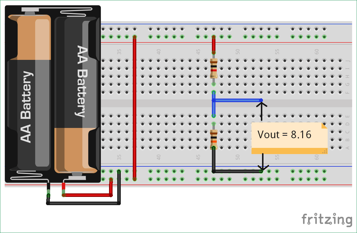
A Voltage or Potential Divider Circuit is commonly used circuit in electronics where an input voltage has to be converted to another voltage lower than then the original. This is very useful for all analog circuits where variable voltages are required, hence it is important to understand how this circuit works and how to calculate the values of the resistors required to make a voltage divider circuit to output the desired voltage.
Material Required
- Resistor (1k – 1 nos, 10k – 1 nos)
- Battery- 9V
- Multi-meter
- Connecting Wires
- Breadboard
Circuit Diagram

A voltage divider circuit is very simple circuit built by only two resistors (R1 and R2) as shown above in the circuit diagrams. The required output voltage (VOUT) can be obtained across the resistor R2. Using these two resistors we can convert an input voltage to any required output voltage.
NOTE: The output voltage (VOUT) is always less than the input voltage (VIN)
Voltage Divider Formula
Assume that, if the current (I) in the output wire is zero, then the relationship between the input voltage (VIN) and output voltage (Vout) is determined as:
VOUT = (VIN * R2) / (R1 + R2) …. (Voltage Divider Equation)
Where,
VOUT = Output Voltage
VIN = Input Voltage
R1 = Upper Resistor
R2 = Lower resistor
Proof of Potential Divider Formula
According to the Ohm’s Law, voltage through an ideal conductor is equal to the current flowing through it.
Voltage = Current * Resistance
V = IR
Now, as per the circuit diagram
VIN = I * (R1 + R2)
I = VIN / (R1 + R2)                               … equation (1)
VOUT = I * R2                                      … equation (2)
On putting the value of ‘I’ from equation (1) into equation (2), we have
VOUT = (VIN * R2) / (R1 + R2)
Things to keep in mind
- If the value of R1 is equal to R2, then the value of the output voltage is half of the input value.
- If the value of R1 is much lesser than R2, then the value of the output voltage will be approximately equal to the input voltage.
- If the value of R1 is much greater than R2, then the value of the output voltage will be approximately equal zero.
Working of Voltage Divider Circuit

As per the example voltage divider circuit diagram we used here, we have taken 9V as the input voltage and value of resistance R1 and R2 is 1k and 10k respectively. Practically we are getting 8.16V as the output voltage as shown in the above image.
Let’s try theoretically,
VIN =9V, R1 = 1 kilo ohms and R2 = 10 kilo ohms.
Vout  = (9×10000) / (1000+10000)
Vout  = (90000) / (11000)
Vout  = 8.1818V
There is a very minor difference between the practical and theoretical value, because the battery does not supply exact 9V.
Another important factor to consider while selecting the resistor values is its power rating (P). Once you know the values of I (based in load), VIN, R1 and R2, add R1 and R2 together to get RTOTAL and use the Ohms law calculator to find out the power (Watts) rating required for the resistors. Or simply use the formulae P=VI to decide on the power rating for your resistor. If a proper Power rating is not selected the resistor will overheat and might also burn. Also if you are completely new to resistors you can use this online resistor color code calculator to find the value of a resistor just by selecting the colour values.
Voltage Divider Calculator
You can also use our Voltage Divider Calculator to calculate any of the values mentioned in the voltage divider formulae.
Applications of Voltage Divider Circuit
Voltage or potential divider circuits are frequently used in various projects and applications. Below are some circuit examples where a potential divider concept is used:


