Circuit Diagram
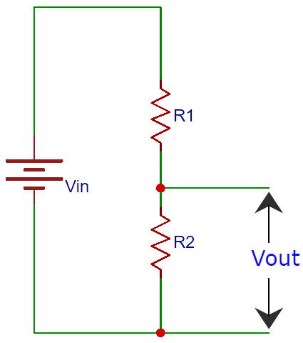
Voltage division across R1 and R2
Use our free online voltage divider calculator to calculate output voltage, input voltage, or resistor values. This resistor divider calculator works with any voltage divider circuit and provides instant results using the standard voltage divider formula.
You can also use this voltage divider circuit calculator to provide any 3 known values in the circuit and calculate the 4th one. Our voltage divider circuit calculator simplifies complex circuit analysis for both beginners and professionals.
Here:
- Vin is the input voltage
- R1 is the resistance of the 1st resistor,
- R2 is the resistance of the 2nd resistor,
- Vout is the output voltage.
Quick Reference
- Formula: Vout = (Vin × R2) / (R1 + R2)
- Current: I = Vin / (R1 + R2)
- Power: P = I² × R or V² / R
- Power across R1 = I² × R1
- Power across R2 = I² × R2
How to use this Resistor Divider Calculator?
You can determine the ideal resistor values or voltages for your circuit with the aid of our Voltage Divider Calculator. Use our voltage divider calculator by following these easy steps.
Voltage Divider Resistance Calculator Features
Comprehensive analysis tools for voltage divider circuits are provided by this resistor divider calculator. Our calculator is the most flexible resistance voltage divider calculator on the internet since it automatically calculates missing values when you enter any three known parameters. Real-time computations, power analysis, and current measurement capabilities are important features.
Choose Your Known Values
The calculator has four fields namely, Input Voltage (Vin), Resistance 1 (R1), Resistance 2 (R2), and Output Voltage (Vout). Out of these four values, the user has to input at least 3 values. When you click on calculate, the calculator will automatically compute the fourth value for you
Pay Attention to Units
Please pay attention to the unit. For Voltages use Volts (V). For resistance choose between Ohms (Ω), Kilohms (kΩ), or Megaohms (MΩ).
How Does Voltage Divider Calculator Work?
A voltage divider resistance calculator is a very common circuit used in electronics where an input voltage has to be converted to another voltage less than it. This circuit is very useful for all analog circuits where variable voltages are required, hence it is important to understand how this circuit works and how to calculate the values of Resistors.
A voltage divider circuit is a very basic circuit with just two resistors (R1 and R2), as seen above. It is possible to obtain the necessary output voltage (Vout) across the resistor R2. With the help of these two resistors, we can change an input voltage into any desired output voltage; the resistance R1 and R2 determine the output voltage. The standard formula, which is displayed below, is used by our voltage divider circuit calculator to determine Vout.
Vout= (Vin x R2) / (R1 + R2)Where, Vout= Output Voltage Vin=Input Voltage and R1=Upper Resistor R2=Lower resistor
We can use the above voltage divider calculator to calculate any one of the values mentioned in the voltage divider formulae, but now let us learn how this formula was derived. Consider the below circuit which can be used to convert 5V input to 3.3V output for analysis

To understand how a potential divider formula is derived, we need a Voltage divider resistance calculator online in ohms. According to Ohm's law, the voltage drop across any location is a product of the current flowing through the circuit and the Resistance across it.
Voltage = Current Flowing through × Resistance across the voltage
Let us use this to calculate the Input Voltage (Vin) for the above circuit. Here there are two resistors across input voltage Vin, hence
Input Voltage = Current × (Resistance 1 + Resistance 2)
Vin = I × (R1 + R2) (1)Similarly, let us calculate for output voltage (Vout), here there is only one resistor (R2) across it, hence
Output Voltage = Current × Resistance R2
Vout = I × R2 (2)If we look at the equations 1 and ,2 we can notice that the value of the current is the same, hence let's rewrite
Equation 1 as, I = Vin / (R1 + R2)
Equation 2 as, I = Vout /R2
Since the current flowing through the circuit is constant, the current I will remain the same for both the equations, hence we can equate them as
Vin / (R1 + R2) = Vout /R2
Vout= (Vin x R2) / (R1 + R2)Voltage Divider Current Calculator
This voltage divider calculator also helps you calculate the current flowing through the circuit. The current in a voltage divider circuit is the same through both resistors since they are in series.
Current Calculation Formula
Current (I) = Vin / (R1 + R2)
Power Consumption Calculation
Total Power = I² × (R1 + R2) or Vin² / (R1 + R2)
Power across R1 = I² × R1
Power across R2 = I² × R2
Voltage Divider Calculator Examples
Example 1: 5V to 3.3V Conversion (Microcontroller Applications)
Input: Vin = 5V, R1 = 1kΩ, R2 = 2kΩ
Calculation: Vout = (5 × 2000) / (1000 + 2000) = 10000 / 3000 = 3.33V
Current: I = 5V / (1kΩ + 2kΩ) = 1.67mA
Application: Perfect for Arduino 5V to 3.3V logic-level conversion
Example 2: Battery Voltage Monitoring
Input: 9V battery, desired output = 4.5V, R1 = 10kΩ
Required R2 = 10kΩ (equal resistor values give half voltage)
Vout = (9 × 10000) / (10000 + 10000) = 4.5V
Current: I = 9V / 20kΩ = 0.45mA (low power consumption)
Example 3: LED Current Limiting Circuit
Input: 12V supply, LED forward voltage = 2V, desired current = 20mA
Required voltage drop = 12V - 2V = 10V
Current limiting resistor = 10V / 0.02A = 500Ω
Power rating needed = 10V × 0.02A = 0.2W (use 0.25W resistor)
Common Application with Solutions
Let's consider a common application in microcontroller circuits where the input voltage (Vin) is 5V and the desired output voltage (Vout) is 3.3V. If we fix the value of R1 at 1kΩ, which is a commonly available resistor, and click on calculate the resulting value for resistor R2 is 1.94kΩ. Now, practically we will not have a resistor with a value of 1.94kΩ, so we will use the closest available resistor, which is 2kΩ
One more common application is in battery voltage division, say we have a 9V battery and our desired output voltage is 5V. Then our Vin is 9V and Vout is 5V. Again if we fix the value of R1 at 4.7kΩ and calculate using this voltage divider resistor calculator, the resulting output for R2 will be R2 = 6.8kΩ. In this case, the resistor 6.8kΩ itself is available, so we can directly use it.
Power Rating Considerations
Another important factor to consider while selecting the resistor values is its power rating (P). Once you know the values of I (based on load), Vin, R1, and R2, add R1 and R2 together to get RTOTAL and use the Ohms law calculator to find out the power(Watts) rating required for the resistors. Or simply use the formulae P=VI to decide on the power rating for your resistor. If a proper Power rating is not selected the resistor will overheat and might also burn.
Tips for Accurate Results
This online voltage divider calculator is highly reliable for a wide range of calculations and applications. But here are a few tips to make sure we get the most accurate results, not just on the calculator but also when you actually build the circuit practically.
Voltage Constraints: The input voltage must be greater than the output voltage and all values must be positive number. The maximum voltage should not be more than 1000V for safety purposes
Resistance Selection: Always use standard resistor values when possible. Consider resistor tolerance (1% or 5%) in your final output, lower tolerance resistor will practically give close to the expected results. Also, remember that higher resistance values reduce power consumption and lower resistance values increase power consumption but provide better stability.
Common Mistakes to Avoid: Don't forget to match units and consider power dissipation. Consider the output power requirement of your load and make sure the your resistance can handle the current required for your load. Remember temperature effects, if the resistor gets hot its resistance value will drop resulting in a different output voltage.
Related Electronics Calculators
For complete circuit design, you might also need these related online electronics calculators:
- Ohms Law Calculator - Calculate voltage, current, resistance, and power
- Resistor Color Code Calculator - Identify resistor values
- LED Resistor Calculator - Calculate current limiting resistors
Voltage Divider vs Other Circuits
Unlike current divider circuits that split current, voltage dividers split voltage proportionally. For AC applications, consider using capacitive voltage dividers instead of resistive ones.
Advanced Voltage Divider Resistance Calculator Applications
Complex circuit analysis, such as cascaded voltage dividers, loaded circuits, and temperature-compensated designs, is supported by this voltage divider circuit calculator. Our voltage divider circuit calculator offers the precision and adaptability required for professional applications, whether you're creating sensor interface circuits or precise reference voltages.
Frequently Asked Questions
⇥ What is a voltage divider calculator used for?
A voltage divider calculator is used to determine the output voltage in a resistive voltage divider circuit. It helps engineers and hobbyists calculate resistor values needed to achieve a specific voltage output from a higher input voltage, commonly used in sensor circuits, reference voltages, and logic level conversion.
⇥ How accurate is this voltage divider calculator?
Our voltage divider calculator provides theoretical accuracy up to 6 decimal places. However, practical accuracy depends on resistor tolerance (typically ±1% to ±5%), temperature effects, and load current. For precision applications, use 1% tolerance resistors and consider the load impedance effects.
⇥ Can I use this calculator for AC voltage dividers?
This calculator is designed for DC voltage dividers using resistors. For AC applications, you'll need to consider impedance rather than just resistance, especially with capacitive or inductive components. The basic voltage division principle remains the same for AC resistive circuits.
⇥ What happens if I don't consider the load current?
Ignoring load current is the most common mistake in voltage divider design. When current flows to your load, it affects the output voltage. For accurate results, ensure your load impedance is at least 10 times higher than R2, or use our current calculations to account for loading effects.
⇥ Why is my calculated voltage different from the measured voltage?
Differences between calculated and measured voltages typically occur due to: resistor tolerance (±5% can cause significant variations), temperature effects, load current drawing additional current, or multimeter input impedance affecting the measurement. Use precision resistors for critical applications.
⇥ Can this voltage divider calculator handle high-voltage applications?
Yes, but exercise extreme caution with high voltages above 50V. Ensure proper power ratings for resistors, consider safety margins, and use appropriate safety measures. The calculator works for voltages up to 1000V, but always follow electrical safety protocols for high voltage work.
This online voltage divider circuit calculator is the most accurate tool for resistance voltage divider calculator analysis. Whether you need a simple voltage divider calculation or complex resistor divider calculations, it handles all scenarios with precision and reliability.
Projects Related To Voltage Divider
We’ve used the voltage divider circuit in a variety of interesting electronics projects. It plays a key role in signal conditioning, sensor interfacing, and voltage scaling. Check out the links below to explore these real-world applications.

A Voltage or Potential Divider Circuit is commonly used circuit in electronics where an input voltage has to be converted to another voltage lower than then the original. This is very useful for all analog circuits where variable voltages are required, hence it is important to understand how this circuit works and how to calculate the values of the resistors required to make a voltage divider circuit to output the desired voltage.

Current Divider Circuits Explained with Formula and Practical Hardware
Similar to the voltage divider, there is another type of circuit called current divider which can be used to divide the total current into several within a closed circuit. So, in this tutorial, we will learn how to build a simple current divider circuit using the resistive method (using only resistors).

Voltage Regulator, as the name suggests, is a circuit that is used to regulate the voltage. Regulated voltage is a smooth supply of voltage, free from any noise or disturbance. The output from the voltage regulator is independent of load current, temperature, and AC line variation.
