

Voltage Regulator, as the name suggests, is a circuit that is used to regulate the voltage. Regulated voltage is a smooth supply of voltage, free from any noise or disturbance. The output from the voltage regulator is independent of load current, temperature, and AC line variation. Engineers can create reliable power supply systems with the aid of these voltage regulator circuit diagrams and schematics. Knowing the circuit board layout is essential for optimum performance, regardless of whether you're looking for a straightforward voltage regulator circuit with a zener diode or intricate switching regulator schematics. Voltage regulators are present in almost every electronic or household appliance, like a TV, a Fridge, a computer, etc, to stabilize the supply voltage.
In simple terms, a voltage regulator minimizes the variation in voltage to protect the device. The voltage regulators in an electrical distribution system are located at a substation or in feeder lines. This line uses two different kinds of regulators. The first is a step regulator, which uses switches to control the current supply. Another is an induction regulator, which is a secondary power source that is an alternating electrical device that resembles an induction motor. It produces a steady output, and a voltage regulator minimizes the variation in voltage to protect the device. There are different types of voltage regulators, which are explained below.
Table of Contents
- Types of Voltage Regulator Circuits
- Linear Voltage Regulator Circuit
- └ 1. Series Voltage Regulator
- └ 2. Shunt Voltage Regulator
- Zener Diode Voltage Regulator Circuit Diagram
- Switching Voltage Regulator
- Buck or Step-Down Switching Voltage Regulator
- Boost or Step-Up Switching Voltage Regulator
- Buck-Boost Switching Voltage Regulator
- Voltage Regulator Component Selection Guide
- Practical Example for Regulator Circuits
- Voltage Regulator Circuit Comparison Table
- Frequently Asked Questions
- Projects using Voltage Regulator Circuits
Types of Voltage Regulator Circuits
Linear Voltage Regulator Circuit
- Series Voltage Regulator
- Shunt Voltage Regulator
Zener Voltage Regulator Circuit
Switching Voltage Regulator Circuit
- Buck type
- Boost type
- Buck/Boost type
Linear Voltage Regulator Circuit
These are the most common regulators used in electronics to maintain a steady output voltage. Linear voltage regulators act like a voltage divider circuit. The linear voltage regulator circuit diagram shows how the variable resistance element maintains a constant output. Some advantages and disadvantages of a linear voltage regulator are given below:
Advantages
- The output ripple voltage is low
- The response is fast
- Less noise
Disadvantages
- Low efficiency
- Large space required
- The output voltage will always be less than the input voltage
1. Series Voltage Regulator
Series Voltage Regulator is a part of the Linear Voltage Regulator and is also called a Series Pass Regulator. A variable element connected in series, is used for maintaining a constant output voltage. The series voltage regulator schematic demonstrates how changing the resistance of the series element varies the voltage drop to ensure a constant output voltage.

As you can see in the circuit diagram for the Series Voltage Regulator, NPN transistor T1 is the series element and a zener diode is used to provide the reference voltage.

When the output voltage increases, the base-emitter voltage decreases, and due to this, transistor T1 conducts less. As T1 conducts less, it reduces the output voltage, hence maintaining the output voltage constant.
The output voltage is defined as:
VO = VZ - VBE
Where,
VO is the output voltage
VZ is Zener breakdown voltage
VBE is base-emitter voltage
2. Shunt Voltage Regulator

The unregulated voltage is directly proportional to the voltage drop across the resistance connected in series, and this voltage drop depends upon the current consumed by the load. The shunt voltage regulator circuit diagram shows how current consumption affects the base current and collector current flow. If the current consumption of the load increases, the base current will also decrease, and due to this, less collector current will flow through the collector emitter terminal hence, the current through the load will increase and vice versa.
The regulated output voltage of the shunt voltage regulator is defined as:
VOUT = VZ + VBE
Zener Diode Voltage Regulator Circuit Diagram

The voltage regulator circuit using a zener diode is one of the simplest and most cost-effective regulation methods. Zener Voltage Regulators are cheaper and only suitable for low-power circuits. It can be used in applications where the amount of power wasted during regulation is not of major concern.
A resistor, is connected in series with the zener diode to limit the amount of current flowing through the diode, and the input voltage Vin (Which must be greater than the zener voltage) is connected across as shown in the image and the output voltage Vout, is taken across the Zener diode with Vout = Vz (Zener Voltage). The Zener diode voltage regulator circuit diagram clearly shows how the Zener diode maintains a constant voltage across its terminals when operating in the reverse breakdown region. So when it starts conducting, it maintains the same voltage across it and allows the extra current, thus providing a stable output voltage.
Learn more about Zener Diode working here.
Switching Voltage Regulator
Switching voltage regulator schematics are more complex but offer higher efficiency compared to linear regulators.
- Buck or Step-Down Switching Voltage Regulator
- Boost or Step-Up Switching Voltage Regulator
- Buck / Boost Switching Voltage Regulator
Buck or Step-Down Switching Voltage Regulator
A Buck Regulator is used to step down the voltage at the output. We can even use the voltage divider circuit to reduce the output voltage, but the efficiency of the voltage divider circuit is low, because resistors dissipate energy as heat. The buck voltage regulator circuit diagram includes a capacitor, a diode, an inductor, and switch components for efficient voltage step-down. We use a capacitor, a diode, an inductor, and a switch in the circuit. The circuit diagram for the Buck Switching Voltage Regulator is given below:

When the switch is ON, the diode remains reverse-biased and the power supply is connected to the inductor. When the switch is open, the polarity of the inductor gets reversed, and the diode becomes forward-biased, and the inductor is connected to ground. Then the current through the inductor decreases with slope:
d IL / dt = (0-VOUT) / L
The Capacitor is used to prevent the voltage from dropping to zero across the load. If we keep opening and closing the switch, the average voltage across the load will be less than the supplied input voltage. You can control the output voltage by varying the duty cycle of the switching device.
Output Voltage = (Input Voltage) * (percentage of time that the switch is ON)
If you want to learn more about a Buck converter, then follow the link.
Boost or Step-Up Switching Voltage Regulator
The Boost Regulator is used to step up the voltage across the load. The circuit diagram for the boost regulator is given below:

When the switch is closed the diode behaves as reversed biased and the current across the inductor keeps increasing. Now, when the switch is opened, the inductor will create a force causing the current to continue flowing, and the capacitor starts charging. By continuously turning the switch ON and OFF, we will receive the voltage at the load higher than the input voltage. We can control the output voltage by controlling the turn-on (Ton) time of the switch.
Output Voltage = Input Voltage / Percentage of time that the switch is open
If you want to learn more about a Boost converter, then follow the link.
Buck-Boost Switching Voltage Regulator
Buck-Boost Switching Regulator is the combination of both Buck and Boost Regulator, it gives inverted output which can be greater or less than the supplied input voltage.

When the switch is ON, the diode behaves as a reverse-bias diode and the inductor stores energy. When the switch is OFF inductor starts releasing the energy with the reverse polarity, which charges the capacitor. When the energy stored in the inductor becomes zero, the capacitor starts discharging into the load with reverse polarity. Due to this buck-boost regulator is also called an inverting regulator.
The output voltage is defined as
Vout = Vin (D / 1-D)
Where, D is the Duty cycle
Hence, if the Duty Cycle is low the regulator behaves as the Buck Regulator and when the Duty Cycle is high the regulator behaves as the Boost Regulator.
Voltage Regulator Component Selection Guide
Type | Selection Criteria | Key Formulas/Notes |
|---|---|---|
Linear Voltage Regulator |
|
|
Zener Diode Regulator |
|
|
Switching Regulator |
|
|
Practical Example for Regulator Circuits
Positive Linear Voltage Regulator Circuit
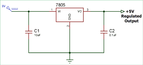
We have designed a positive linear voltage regulator circuit using 7805 IC. This voltage regulator circuit board design demonstrates practical implementation using the popular 7805 voltage regulator IC. This IC has all the circuitry to provide a 5-volt regulated supply. The input voltage should be at least more than 2V above the rated value, like for LM7805, we should at least provide 7V.
Unregulated input voltage is supplied to the IC and we get regulated voltage at the output terminal. The name of the IC defines its function, 78 represents the positive sign, and 05 represents the value of the regulated output voltage. As you see in the circuit diagram we are giving 9V to the 7805IC and getting regulated +5V at the output. The capacitors C1 and C2 are used for filtration.

Zener Voltage Regulator Circuit
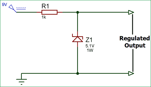
Here, we have designed a Zener Voltage Regulator using a 5.1V of Zener diode. This practical voltage regulator circuit, using a zener diode, showcases the simplest form of voltage regulation suitable for low-power applications. The Zener diode works as the sensing element. When the supply voltage exceeds its breakdown voltage, it starts conducting in the reverse direction and maintains the same voltage across it and allowing the extra current, thus providing a stable output voltage. In this circuit, we are giving 9V of input voltage and getting nearly 5.1 voltage of regulated output.

Voltage Regulator Circuit Comparison Table
Regulator Type | Efficiency | Complexity | Cost | Best Use Case |
Linear Series | 30-60% | Low | Low | Low-noise audio circuits |
Zener Diode | 25-50% | Very Low | Very Low | Simple reference circuits |
Buck Switching | 80-95% | Medium | Medium | High current applications |
Boost Switching | 75-90% | Medium | Medium | Battery-powered devices |
Frequently Asked Questions
⇥ What distinguishes switching voltage regulators from linear voltage regulators?
Although linear voltage regulators have a smooth, low-noise output, their efficiency is lower (30–60%). Higher efficiency (80–95%) can be achieved with switching voltage regulators, but switching noise may be introduced.
⇥ How can I choose the best circuit diagram for a voltage regulator for my project?
Take into account the required output current, input voltage range, efficiency requirements, and financial limitations. For straightforward, low-power applications, use zener diode circuits. If you need low noise, go with linear regulators. For high-current, high-efficiency applications, choose switching regulators.
⇥ Which essential parts are required for the circuit board of a voltage regulator?
The regulator IC/transistor, input/output capacitors, feedback resistors (for adjustable types), heat sink (for high current), and protection diodes are all necessary parts. Faster switching diodes and inductors are also required for switching regulators.
Projects using Voltage Regulator Circuits
These voltage regulation techniques have powered many of our previous DIY circuits—check out the projects listed below.

High Current Low Dropout Voltage Regulator Circuit using MIC29302
In this project, we will use MIC29302 to build an LDO regulator or Low Dropout Regulator Circuit. The output voltage can be changed using high or low-value resistors at the adjusting pin.
")
Simple Variable Voltage Dual Power Supply Circuit (-14V to 14V)
In this tutorial, we are going to design a variable dual DC power supply circuit that can provide a variable output voltage ranging from 14V to -14V. The voltage conversion task is performed in four steps, which are Transformer operation, Rectification, Smoothing, and Regulation.

Design a Voltage Controlled Current Source Circuit using Op-Amp
In this project, we will explain how a voltage-controlled current source using op-amp can be designed and also build it to demonstrate its working. This type of voltage-controlled current source circuit is also called a current servo.
