
One common feature that is used in almost every embedded application is the ADC module (Analog to Digital Converter). These Analog to digital Converters can read voltage from analog sensors like Temperature sensor, Tilt sensor, Current sensor, Flex sensor and much more. So in this tutorial we will learn how to use ADC in STM32F103C8 to read Analog voltages using the Energia IDE. We will interface a small potentiometer to STM32 Blue Pill board and supply a varying voltage to an Analog pin, read the voltage and display it on the 16x2 LCD screen.
Comparing ADC in Arduino and STM32F103C8
In Arduino board, it contains a 6 channel (8 channels on the Mini and Nano, 16 on the Mega), 10-bit ADC with an input voltage range of 0V–5V. This means that it will map input voltages between 0 and 5 volts into integer values between 0 and 1023. Now in the case of STM32F103C8 we have 10 channels, 12-Bit ADC with an input range 0V -3.3V. It will map input voltages between 0 and 3.3 volts into integer values between 0 and 4095.
ADC in STM32
The ADC embedded in STM32 microcontrollers uses the SAR (successive approximation register) principle, by which the conversion is performed in several steps. The number of conversion steps is equal to the number of bits in the ADC converter. Each step is driven by the ADC clock. Each ADC clock produces one bit from result to output. The ADC internal design is based on the switched-capacitor technique. If you are new to STM32, then checkout our Getting started with STM32 tutorial.
12-bit Resolution
This ADC is a 10 channel 12 -bit ADC. Here the term 10 channel implies that there are 10 ADC pins using which we can measure analog voltage. The term 12-bit implies the resolution of the ADC. 12-bit means 2 to the power of ten (212) which is 4096. This is the number of sample steps for our ADC, so the range of our ADC values will be from 0 to 4095. The value will increase from 0 to 4095 based on the value of voltage per step, which can be calculated by formula
VOLTAGE / STEP = REFERENCE VOLTAGE / 4096 = (3.3/4096= 8.056mV) per unit.
How an Analog Signal is converted into Digital Format
As computers store and process only binary/digital values (1’s and 0’s). So Analog signals like sensor’s output in volts has to be converted into digital values for processing and the conversion needs to be accurate .When a input analog voltage is given to STM32 at its Analog inputs, the analog value is read and stored in a integer variable. That stored Analog value(0-3.3V ) is converted into integers values (0-4096) using the formula below:
INPUT VOLTAGE = (ADC Value / ADC Resolution) * Reference Voltage
Resolution = 4096
Reference = 3.3V
ADC Pins in STM32F103C8T6

There are 10 Analog Pins in STM32 from PA0 to PB1.
Also check how to use ADC in other Microcontrollers:
- How to Use ADC in Arduino Uno?
- Interfacing ADC0808 with 8051 Microcontroller
- Using ADC Module of PIC Microcontroller
- Raspberry Pi ADC Tutorial
- How to use ADC in MSP430G2 - Measuring Analog Voltage
Components Required
- STM32F103C8
- LCD 16*2
- Potentiometer 100k
- Breadboard
- Connecting wires
Circuit Diagram and Explanations
The circuit diagram to interface 16*2 LCD and Analog Input to a STM32F103C8T6 board is shown below.

The connections which are done for LCD are given below:
|
LCD Pin No |
LCD Pin Name |
STM32 Pin Name |
|
1 |
Ground (Gnd) |
Ground (G) |
|
2 |
VCC |
5V |
|
3 |
VEE |
Pin from Centre of Potentiometer |
|
4 |
Register Select (RS) |
PB11 |
|
5 |
Read/Write (RW) |
Ground (G) |
|
6 |
Enable (EN) |
PB10 |
|
7 |
Data Bit 0 (DB0) |
No Connection (NC) |
|
8 |
Data Bit 1 (DB1) |
No Connection (NC) |
|
9 |
Data Bit 2 (DB2) |
No Connection (NC) |
|
10 |
Data Bit 3 (DB3) |
No Connection (NC) |
|
11 |
Data Bit 4 (DB4) |
PB0 |
|
12 |
Data Bit 5 (DB5) |
PB1 |
|
13 |
Data Bit 6 (DB6) |
PC13 |
|
14 |
Data Bit 7 (DB7) |
PC14 |
|
15 |
LED Positive |
5V |
|
16 |
LED Negative |
Ground (G) |
The connections are made according to the above given table. There are two Potentiometers present in the circuit, first one is used for voltage divider which can be used to vary voltage and provide analog input to STM32. Left pin of this potentiometer gets input positive voltage from STM32 (3.3V) and right pin is connected to ground, centre pin of potentiometer is connected to analog input pin (PA7) of STM32. The other potentiometer is used to vary the contrast of the LCD display. The power source for STM32 is provided by means of USB power supply from a PC or Laptop.
Programming STM32 for reading ADC values
In our previous tutorial, we learned about Programming STM32F103C8T6 Board using USB Port . So we don’t need a FTDI programmer now. Simply connect it to PC via USB port of STM32 and start programming with ARDUINO IDE. Programming your STM32 in ARDUINO IDE to read analog voltage is very simple. It is same like arduino board. There is no need of changing the jumper pins of STM32.
In this program will read the analog value and calculate the voltage with that value and then display both, analog and digital values, on the LCD screen.
First define out LCD pins. These define to which pin of STM32 the LCD pins are connected. You can modify as per your requirements.
const int rs = PB11, en = PB10, d4 = PB0, d5 = PB1, d6 = PC13, d7 = PC14; //mention the pin names to with LCD is connected to
Next, we include the header file for the LCD display. This calls the library which contains the code for how the STM32 should communicate with the LCD. Also make sure the function Liquid Crystal is called with the pin names that we just defined above.
#include <LiquidCrystal.h> // include the LCD library
LiquidCrystal lcd(rs, en, d4, d5, d6, d7); //Initialize the LCD
Inside the setup() function, we would just give an intro message to be displayed in the LCD screen. You can learn about interfacing LCD with STM32.
lcd.begin(16, 2); //We are using a 16*2 LCD
lcd.clear(); //Clear the screen
lcd.setCursor(0, 0); //At first row first column
lcd.print("CIRCUITDIGEST"); //Print this
lcd.setCursor(0, 1); //At secound row first column
lcd.print("STM32F103C8"); //Print this
delay(2000); //wait for two secounds
lcd.clear(); //Clear the screen
lcd.setCursor(0, 0);  //At first row first column
lcd.print("USING ADC IN");//Print this
lcd.setCursor(0,1); //At secound row first column
lcd.print("STM32F103C8");//Print this
delay(2000); //wait for two secounds
lcd.clear(); //Clear the screen
Finally, inside our infinite loop() function, we start reading the analog voltage supplied to the PA7 pin from potentiometer. As we discussed already, the microcontroller is a digital device and it cannot read voltages level directly. Using SAR technique the voltage level is mapped from 0 to 4096. These values are called the ADC values, to get this ADC value simply use the following line
int val = analogRead(A7); // read the ADC value from pin PA7
Here the function analogRead() is used to read the analog value of the pin. Finally we save this value in a variable called “val”. The type of this variable is integer because we will only get values ranging from 0 to 4096 to be stored in this variable.
The next step would be to calculate the voltage value from the ADC value. To do this we have the following formulae
Voltage = (ADC Value / ADC Resolution) * Reference Voltage
In our case we already know that the ADC resolution of our microcontroller is 4096. The ADC value is also found in the previous line and stored the variable called val. The reference voltage is equal to the voltage at which the microcontroller is operating. When the STM32 board is powered via USB cable then the operating voltage is 3.3V. You can also measure the operating voltage by using a multimeter across the Vcc and ground pin on the board. So the above formula fits into our case as shown below
float voltage = (float(val)/4096) * 3.3; //formulae to convert the ADC value to voltage
You might be confused with the line float (val). This is used to convert the variable “val” from int data type to “float” data type. This conversion is needed because only if we get the result of val/4096 in float we can multiply it 3.3. If the value is received in integer it will always be 0 and the result will also be zero. Once we have calculated the ADC value and voltage, all that is left is to display the result on the LCD screen which can be done by using the following lines
lcd.setCursor(0, 0); // set the cursor to column 0, line 0
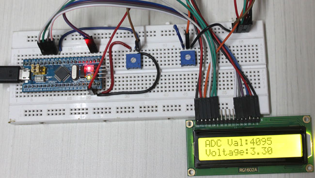
lcd.print("ADC Val:");
lcd.print(val); //Display ADC value
lcd.setCursor(0, 1); // set the cursor to column 0, line 1
lcd.print("Voltage:");
lcd.print(voltage); //Display voltage
Complete code and Demonstration Video is given below.
Complete Project Code
#include <LiquidCrystal.h> // include the LCD library

const int rs = PB11, en = PB10, d4 = PB0, d5 = PB1, d6 = PC13, d7 = PC14; //mention the pin names to with LCD is connected to

LiquidCrystal lcd(rs, en, d4, d5, d6, d7); //Initialize the LCD

const int analogip = PA7;//Initialize the analog input pin

void setup()

{

  lcd.begin(16, 2); //We are using a 16*2 LCD

  lcd.clear(); //Clear the screen

  lcd.setCursor(0, 0); //At first row first column

  lcd.print("CIRCUITDIGEST"); //Print this

  lcd.setCursor(0, 1); //At secound row first column

  lcd.print("STM32F103C8"); //Print this

  delay(2000); //wait for two secounds

  lcd.clear(); //Clear the screen

  lcd.setCursor(0, 0);  //At first row first column

  lcd.print("USING ADC IN");//Print this

  lcd.setCursor(0,1); //At secound row first column

  lcd.print("STM32F103C8");//Print this

  delay(2000); //wait for two secounds

  lcd.clear(); //Clear the screen

}

void loop()

{

  int val = analogRead(PA7);    // read the ADC value from pin A7

  float voltage = (float(val)/4096) * 3.3; //formulae to convert the ADC value to voltage

  lcd.setCursor(0, 0);   // set the cursor to column 0, line 0

  lcd.print("ADC Val:");

  lcd.print(val); //Display ADC value

  lcd.setCursor(0, 1);   // set the cursor to column 0, line 1

  lcd.print("Voltage:");

  lcd.print(voltage); //Display voltage

}
