
")
For any microcontroller project, interfacing a display unit with it would make the project a lot easier and appealing for the user to interact with. The most commonly used display unit for microcontrollers is the 16×2 Alpha numeric displays. These types of displays are not only useful to display vital information to the user but can also act as a debugging tool during the initial developmental stage of the project. So, in this tutorial we will learn how we can interface a 16×2 LCD display with the STM32F103C8T6 STM32 Development board and program it using the Arduino IDE. For people who are familiar with Arduino this tutorial will just be a cake walk since they both are very similar. Also to learn more about STM32 Blue Pill Board follow our getting started tutorial.
Materials Required
- STM32 Blue Pill Development Board
- 16×2 LCD display
- FTDI Programmer
- Connecting Wires
- LCD
Brief Intro to 16×2 Dot matrix LCD display
As told earlier the Energia IDE provides a beautiful library which makes the interfacing a piece of cake and hence it’s not mandatory to know anything about the display module. But, would didn’t it be interesting to show what we are using!!
The name 16×2 implies that the display has 16 Columns and 2 Rows, which together (16*2) forms 32 boxes. One single box would look something like this in the picture below
![]()
A single box has 40 pixels (dots) with a matrix order of 5 Rows and 8 columns, these 40 pixels together forms one character. Similarly, 32 characters can be displayed using all the boxes. Now lets take a look at the pinouts.

The LCD has a total of 16 Pins, as shown above, they can be categorized into four groups like as follows
Source Pins (1, 2 and 3): These pins source the power and contrast level for the display
Control Pins (4, 5 and 6): These pins sets/controls the registers in the LCD interfacing IC (more this can be found in link below)
Data/Command Pins (7 to 14): These pins provide the data of what information should be displayed on the LCD.
LED pins (15 and 16): These pins are used to glow the backlight of LCD if needed (optional).
Out of all these 16 pins, only 10 pins are to be used mandatory for the proper working of the LCD if you want to know more about these LCD display jump to this 16x2 LCD article.
Circuit Diagram and Connection
The circuit diagram to interface 16*2 Dot matrix LCD with STM32F103C8T6 STM32 Blue Pill board is shown below. It is made using the Fritzing Software.

As you can see the complete connection is made over a breadboard. We need a FTDI board to program the STM32 Microcontroller. So similar to our previous tutorial, we have wired the FTDI board to STM32, the Vcc and ground pin of the FDTI programmer is connected to the 5V pin and ground pin of the STM32 respectively. This is used to power the STM32 board and the LCD since both can accept can +5V. The Rx and Tx pin of the FTDI board is connected to the A9 and A10 pin of the STM32 so that we can program the board directly without the boot loader.
Next the LCD has to be connected to the STM32 board. We are going to use the LCD in 4-bit mode, so we have to connect the 4 data bit pins (DB4 to DB7) and the two control pin (RS and EN) to the STM32 board as shown in the STM32F103C8T6 LCD interfacing circuit diagram above. Further the table below will help you in making the connection.
LCD Pin No. | LCD Pin Name | STM32 Pin Name |
1 | Ground (Gnd) | Ground (G) |
2 | VCC | 5V |
3 | VEE | Ground (G) |
4 | Register Select (RS) | PB11 |
5 | Read/Write (RW) | Ground (G) |
6 | Enable (EN) | PB10 |
7 | Data Bit 0 (DB0) | No Connection (NC) |
8 | Data Bit 1 (DB1) | No Connection (NC) |
9 | Data Bit 2 (DB2) | No Connection (NC) |
10 | Data Bit 3 (DB3) | No Connection (NC) |
11 | Data Bit 4 (DB4) | PB0 |
12 | Data Bit 5 (DB5) | PB1 |
13 | Data Bit 6 (DB6) | PC13 |
14 | Data Bit 7 (DB7) | PC14 |
15 | LED Positive | 5V |
16 | LED Negative | Ground (G) |
Once the connections are done we can open the Arduino IDE and start programming it.
Programming STM32 for LCD using Arduino
As told in this tutorial we will be using the Arduino IDE to program our STM32 Microcontroller. But, the Arduino IDE by default will not have the STM32 board installed, hence we have to download a package and prepare the Arduino IDE for the same. This is exactly what we did in our previous tutorial getting started with STM32F103C8T6 using Arduino IDE. So if you have not installed the required packages fall back to this tutorial and follow it before you continue here.
Once the STM32 Board is installed in the Arduino IDE, we can start programming. The program is very similar to that of an Arduino board, the only thing that will change are the pin names since the notations are different for STM32 and Arduino. The complete program is given at the end of this page, but to explain the program I have split it into small meaningful snippets as shown below.
One noticeable advantage of using Arduino for programming our microcontrollers is that Arduino has readymade libraries for almost every famous sensors and actuators. So here we start our program by including the LCD library which makes the programming a lot easier.
#include <LiquidCrystal.h> // include the LCD library
In the next line we have to specify to which GPIO pins of the STM32 we have connected the LCD display control and data lines. To do this we have to check our hardware, for ease you can also refer to the table given at the top which lists the pin names of LCD against the GPIO pin of STM32. After mentioning the pins we can initialise the LCD using the LiquidCrystal function. We also name our LCD as “lcd” as shown below.
const int rs = PB11, en = PB10, d4 = PB0, d5 = PB1, d6 = PC13, d7 = PC14; //mention the pin names to with LCD is connected to
LiquidCrystal lcd(rs, en, d4, d5, d6, d7); //Initialize the LCD
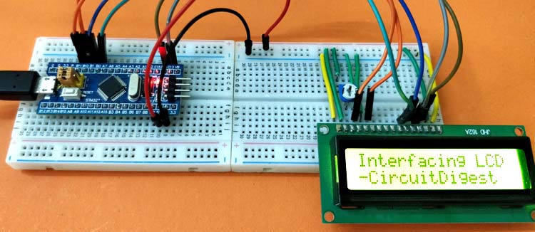
Next we step inside the setup function. Here first we have mention what type of LCD we are using. Since it is a 16*2 LCD we use the line lcd.begin(16,2). The code inside the void setup function gets executed only once. So we use it to display an intro text which comes on the screen for 2 seconds and then gets cleared. To mention the position where the text has to appear we use the function lcd.setcursor and to print the text we use the lcd.print function. For instance lcd.setCursor(0,0) will set the cursor at first row and first column where we print “Interfacing LCD” and the function lcd.setCursor (0,1) moves the cursor to second row first column where we print the line “CircuitDigest”.
void setup() {
  lcd.begin(16, 2);//We are using a 16*2 LCD
  lcd.setCursor(0, 0); //At first row first column
  lcd.print("Interfacing LCD"); //Print this
  lcd.setCursor(0, 1); //At secound row first column
  lcd.print("-CircuitDigest"); //Print this
  delay(2000); //wait for two secounds
  lcd.clear(); //Clear the screen
}
After displaying the intro text we hold the program for 2 seconds by creating a delay so that the user the can read the intro message. This delay is created by the line delay(2000) where 2000 is the delay value in mill seconds. After the delay we clear the LCD using the lcd.clear() function which clears the LCD by removing all the text on LCD.
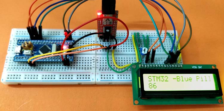
Finally inside the void loop, we display “STM32 –Blue Pill” on the first line and the value of seconds on the second line. The value of second can be obtained from the millis() function. The millis() is a timer which gets incrementing right from the time the MCU is powered. The value is in form of milli seconds so we divide it by 1000 before displaying it on our LCD.
void loop() {
  lcd.setCursor(0, 0); //At first row first column
  lcd.print("STM32 -Blue Pill"); //Print this
  lcd.setCursor(0, 1); //At secound row first column
  lcd.print(millis() / 1000); //Print the value of secounds
}
Uploading the Program to STM32F103C8T6 Board
Make the connections as show in the circuit diagram and use the code given below on Arduino IDE. Go to tools and make sure the right board is selected as done in getting started tutorial. Also, before uploading the program make sure the boot 0 jumper is set to 1 as shown in the image below and press the reset button. When the upload button is pressed is code should get uploaded and the message will be shown on LCD as show in the image below.
Verifying the Output on Operating Mode
As discussed in the above paragraph you should be able to notice the output as soon as the code is uploaded. But this program will not work the next time when you power up the board, since the board is still in programming mode. So once the program is uploaded the jumper on boot 0 should be changed back to 0 positions as show below. Also now since the program is uploaded to the STM32 board already we do not need the FTDI board and the whole set-up can be powered by the micro-USB port of the STM32 board as well as shown below.
This is just a simple interfacing project to help use the LCD display with STM32 board, but further you can use this to build cool projects. Hope you understood the tutorial and learnt something useful from it. If you had faced any problem in getting it to work, please use the comment section to post the problem or use the forums for other technical questions. The complete working of LCD display with STM32 can also be found as a video given below.
Complete Project Code
/*
Program to test 16*2 Alaphanumeric LCD with STM32 (Blue Pill)
For: www.circuitdigest.com
  The circuit:
 * LCD RS pin to digital pin PB11
 * LCD Enable pin to digital pin PB10
 * LCD D4 pin to digital pin PB0
 * LCD D5 pin to digital pin PB1
 * LCD D6 pin to digital pin PC13
 * LCD D7 pin to digital pin PC14
 * LCD R/W pin to ground
 * LCD VSS pin to ground
 * LCD VCC pin to 5V
*/

#include <LiquidCrystal.h> // include the LCD library
const int rs = PB11, en = PB10, d4 = PB0, d5 = PB1, d6 = PC13, d7 = PC14; //mention the pin names to with LCD is connected to
LiquidCrystal lcd(rs, en, d4, d5, d6, d7); //Initialize the LCD
void setup() {
  lcd.begin(16, 2);//We are using a 16*2 LCD
  lcd.setCursor(0, 0); //At first row first column
  lcd.print("Interfacing LCD"); //Print this
  lcd.setCursor(0, 1); //At secound row first column
  lcd.print("-CircuitDigest"); //Print this

  delay(2000); //wait for two secounds
  lcd.clear(); //Clear the screen
}
void loop() {
  lcd.setCursor(0, 0); //At first row first column
  lcd.print("STM32 -Blue Pill"); //Print this
  lcd.setCursor(0, 1); //At secound row first column
  lcd.print(millis() / 1000); //Print the value of secounds
}

Good projects