

Understanding the ADC module:
Trust me, it would hardly take 10 minutes to connect and program the MSP430G2 to read Analog voltage. But, let us spend some time in understanding the ADC module in the MSP board so that we will be able to use it effectively in all our upcoming projects.
A microcontroller is a digital device, meaning it can understand only 1’s and 0’s. But in real world, almost everything like temperature, humidity, wind speed, etc. are analog in nature. In order to interact with these analog changes, the microcontroller uses a module called ADC. There are many different types of ADC modules available, the one used in our MSP is the SAR 8 channel 10-bit ADC.
Successive Approximation (SAR) ADC: The SAR ADC works with the help of a comparator and some logic conversations. This type of ADC uses a reference voltage (which is variable) and compares the input voltage with the reference voltage using a comparator and difference, which will be a digital output, is saved from the Most significant bit (MSB). The speed of the comparison depends on the Clock frequency (Fosc) on which the MSP is operating.
10-bit Resolution: This ADC is an 8 channel 10 bit ADC. Here the term 8 channel implies that there are 8 ADC pins using which we can measure analog voltage. The term 10-bit implies the resolution of the ADC. 10-bit means 2 to the power of ten (210) which is 1024. This is the number of sample steps for our ADC, so the range of our ADC values will be from 0 to 1023. The value will increase from 0 to 1023 based on the value of voltage per step, which can be calculated using the below formula

Note: By default in Energia the reference voltage will be set to Vcc (~3v), you can vary the reference voltage by using the analogReference() option.
Also check how to interface ADC with other Microcontrollers:
- How to Use ADC in Arduino Uno?
- Interfacing ADC0808 with 8051 Microcontroller
- Using ADC Module of PIC Microcontroller
- Raspberry Pi ADC Tutorial
Circuit Diagram:
In our previous tutorial we already learned how to interface LCD with MSP430G2 , now we are just going to add a potentiometer to the MSP430 to supply it a variable voltage and display the voltage value on the LCD. If you are not aware of interfacing the LCD then fall back to the link above and read through it, since I will be skipping the information to avoid repentance. The complete circuit diagram of the project is given below.

As you can see there are two potentiometers used here, one is used for setting the contrast of LCD while the other one is used to supply a variable voltage to the board. In that potentiometer one extreme end of the potentiometer is connected to the Vcc and the other end is connected to Ground. The centre pin (blue wire) is connected to the pin P1.7. This pin P1.7 will provide a variable voltage from 0V (ground) to 3.5V (Vcc). So we have to program the pin P1.7 to read this variable voltage and display it on the LCD.
In Energia, we need to know to which analog channel the pin P1.7 belongs to? This can be found by referring the below picture

You can see P1.7 pin on the right-hand side, this pin belongs to A7 (Channel 7). Similarly, we can find the respective channel number for other pins as well. You can use any pins from A0 to A7 for reading analog voltages here I have selected A7.
Programming your MSP430 for ADC:
Programming your MSP430 to read analog voltage is very simple. In this program will read the analog of value and calculate the voltage with that value and then display both on the LCD screen. The complete program can be found at the bottom of this page, further below I am explaining the program in snippets to help you understand better.
We begin by defining out LCD pins. These define to which pin of MSP430 the LCD pins are connected. You can refer you connection to make sure that the pins are connected respectively
#define RS 2
#define EN 3
#define D4 4
#define D5 5
#define D6 6
#define D7 7
Next, we include the header file for the LCD display. This calls the library which contains the code on how the MSP should communicate with the LCD. This library will be installed in the Energia IDE by default so you need not bother adding it. Also make sure the function Liquid Crystal is called with the pin names that we just defined above.
#include <LiquidCrystal.h> //This librarey is insatlled by default along with IDE
LiquidCrystal lcd(RS, EN, D4, D5, D6, D7); //Let the librarey know how we have connected the LCD
Inside our setup() function, we would just give an intro message to be displayed in the LCD screen. I am not getting in much deep since we have already learnt how to use LCD with MSP430G2.
  lcd.begin(16, 2); //We are using a 16*2 LCD display
  lcd.setCursor (0,0); //Place the cursor at 1st row 1st column
  lcd.print("MSP430G2553"); //Display a intro message
  lcd.setCursor(0, 1);   // set the cursor to 1st column 2nd row
  lcd.print("-CircuitDigest"); //Display a intro message
Finally, inside our infinite loop() function, we start reading the voltage supplied to the A7 pin. As we discussed already the microcontroller is a digital device and it cannot read voltages level directly. Using SAR technique the voltage level is mapped from 0 to 1024. These values are called the ADC values, to get this ADC value simply use the following line
int val = analogRead(A7); // read the ADC value from pin A7
Here the function analogRead() is used to read the analog value of the pin, we have specified A7 inside it since we have connected out variable voltage to pin P1.7. Finally we save this value in a variable called “val”. The type of this variable is integer because we will only get values ranging from 0 to 1024 to be stored in this variable.
The next step would be to calculate the voltage value from the ADC value. To do this we have the following formulae
Voltage = (ADC Value / ADC Resolution) * Reference Voltage
In our case we already know that the ADC resolution of our microcontroller is 1024. The ADC value is also found in the previous line and stored the variable called val. The reference voltage is equal to the voltage at which the microcontroller is operating. When the MSP430 board is powered via USB cable then the operating voltage is 3.6V. You can also measure the operating voltage by using a multimeter across the Vcc and ground pin on the board. So the above formula fits into our case as shown below
float voltage = (float(val)/1024) * 3.6; //formulae to convert the ADC value to voltage
You might be confused with the line float (val). This is used to convert the variable “val” from int data type to “float” data type. This conversion is needed because only if we get the result of val/1024 in float we can multiply it 3.6. If the value is received in integer it will always be 0 and the result will also be zero. Once we have calculated the ADC value and voltage, all that is left is to display the result on the LCD screen which can be done by using the following lines
  lcd.setCursor(0, 0);   // set the cursor to column 0, line 0
  lcd.print("ADC Val:");
  lcd.print(val); //Display ADC value
  lcd.setCursor(0, 1);   // set the cursor to column 0, line 1
  lcd.print("Voltage:");
  lcd.print(voltage); //Display voltage
Here we have displayed the value of ADC in the first line and the value of Voltage in the second line. Finally we give a delay of 100 mill seconds and clear the LCD screen. This was the value will get updated for every 100 mils.
Testing your result!
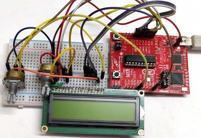
Finally, we come down to the fun part, which is testing our program and playing around with it. Just make the connections as shown in the circuit diagram. I have used a small breadboard to make my connections and used jumper wires to connect the breadboard to MSP430. Once the connections are done mine looked like this below.
Then upload the program which is given below to the MSP430 board through the Energia IDE. You should be able to see the intro text on the LCD, if not adjust the contrast of the LCD using the potentiometer until you see clear words. Also, try pressing the reset button. If things work as expected then you should be able to see the following screen.
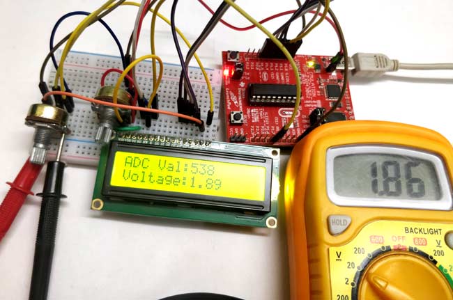
Now vary the potentiometer and you should also see the voltage displayed in the LCD getting varied. Let us verify if we are measuring the voltage correctly to do that, use a multimeter to measure the voltage across the centre of the POT and the ground. The voltage displayed on the multimeter should be close to the value displayed on the LCD as shown in the picture below.
That is it, we have learnt how to measure analog voltage using ADC of MSP430 board. Now we can interface many analog sensors with our board to read real time parameters. Hope you understood the tutorial and enjoyed learning it, if you have any problems please reach out through the comment section below or through the forums. Let’s catch up in another tutorial of MSP430 with another new topic.
Complete Project Code
/*

 * Reading Analog Voltage with MSP430 using Energia

 */
#define RS 2

#define EN 3

#define D4 4

#define D5 5

#define D6 6

#define D7 7

#include <LiquidCrystal.h> //This librarey is insatlled by default along with IDE

LiquidCrystal lcd(RS, EN, D4, D5, D6, D7); //Let the librarey know how we have connected the LCD
void setup() {

  lcd.begin(16, 2); //We are using a 16*2 LCD display

  lcd.setCursor (0,0); //Place the cursor at 1st row 1st column

  lcd.print("MSP430G2553"); //Display a intro message

  lcd.setCursor(0, 1);   // set the cursor to 1st column 2nd row

  lcd.print("-CircuitDigest"); //Display a intro message


   delay(2000); //Wait for display to show info

   lcd.clear(); //Then clean it
}

void loop() {

  int val = analogRead(A7);    // read the ADC value from pin A7

  Voltage = (ADC Value / ADC Resolution) * Reference Voltage

  float voltage = (float(val)/1024) * 3.6; //formulae to convert the ADC value to voltage


  lcd.setCursor(0, 0);   // set the cursor to column 0, line 0

  lcd.print("ADC Val:");

  lcd.print(val); //Display ADC value

  lcd.setCursor(0, 1);   // set the cursor to column 0, line 1

  lcd.print("Voltage:");

  lcd.print(voltage); //Display voltage


}

Good content