
ADC is the Analog to Digital converter, which converts analog data into digital format; usually, it is used to convert analog voltage into digital format. Analog signal has an infinite no of values, like a sine wave or our speech, ADC converts them into particular levels or states, which can be measured in numbers as a physical quantity. Instead of continuous conversion, ADC converts data periodically, which is usually known as the sampling rate. A telephone modem is an example of ADC, which is used for the internet. It converts analog data into digital data, so that the computer can understand, because the computer can only understand Digital data. The major advantage of using ADC is that the noise can be efficiently eliminated from the original signal and the digital signal can travel more efficiently than analog one. That’s the reason that digital audio is very clear while listening. Master the art of interfacing ADC with 8051 microcontroller using ADC0808
In the present time, there are lots of microcontrollers on the market which has an inbuilt ADC with one or more channels. And by using their ADC register, we can interface. When we select the 8051 microcontroller family for making any project, in which we need an ADC conversion, then we use an external ADC. Some external ADC chips are 0803,0804,0808,0809, and there are many more. Today, we are going to interface an 8-channel ADC with the AT89s52 Microcontroller, namely ADC0808/0809.
Table of Contents
What is ADC (Analog to Digital Converter)?
Analog to Digital converters, or ADCs, are electronic components that can take an infinite set of analog values and condense them into a finite number of digitised values. In microcontroller projects, analog to digital converter interfacing with 8051 enables the system to process real-world analog data like temperature, pressure, or voltage levels.
Key Features of ADC in Microcontroller Systems:
» Signal Conversion: converts infinite values of analog signals into finite digital states.
» Sampling Rate: defines the frequency of conversion so that the ADC can continuously monitor.
» Resolution: maps levels of accuracy - for example, an 8-bit resolution ADC converts a signal into 256 levels, while a 12-bit resolution ADC converts a signal into 4096 different levels.
» Noise Immunity: digital signals have more immunity against noise.
» Processing: the microcontroller can process the real-world input
Components Required for ADC Interfacing with 8051
To implement ADC 0808 interfacing with 8051, gather these essential components for a complete analog to digital conversion system:
- 8051 Microcontroller (AT89S52)
- ADC0808/0809
- 16x2 LCD
- Resistor (1k,10k)
- POT(10k x4)
- Capacitor(10uf,1000uf)
- Red led
- Breadboard or PCB
- 7805
- 11.0592 MHz Crystal
- Power
- Connecting wires
ADC0808/0809 Microcontroller Interface Chip
ADC0808/0809 is a monolithic CMOS device and microprocessor-compatible control logic with 28 pins, which gives an 8-bit value in output and 8-channel ADC input pins (IN0-IN7). Its resolution is 8, so it can encode the analog data into one of the 256 levels (28). The ADC0808 interfacing with 8051 project utilises a high-performance 8-bit analog to digital converter with 8 input channels. This device has three channel address lines, namely: ADDA, ADDB and ADDC for selecting a channel. Below is the Pin Diagram for ADC0808:
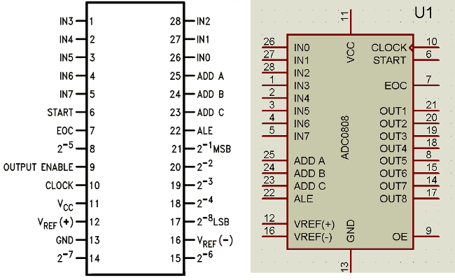
ADC0808/0809 requires a clock pulse for conversion. We can provide it by using an oscillator or a microcontroller. In this project, we have applied frequency by using a microcontroller.
ADC0808/0809 Technical Specifications
| Parameter | Specification | Description |
| Resolution | 8-bit | 256 discrete output levels (2⁸) |
| Input Channels | 8 channels (IN0-IN7) | Multiplexed analog inputs |
| Supply Voltage | +5V | Compatible with TTL/CMOS logic |
| Conversion Time | 100μs typical | With 500kHz clock frequency |
| Package | 28-pin DIP | Standard breadboard compatible |
We can select any input channel by using the Address lines, like we can select the input line IN0 by keeping all three address lines (ADDA, ADDB and ADDC) Low. If we want to select input channel IN2, then we need to keep ADDA, ADDB low and ADDC high. For selecting all the other input channels, have a look at the given table:
ADC Channel Name | ADDC PIN | ADDB PIN | ADDA PIN |
IN0 | LOW | LOW | LOW |
IN1 | LOW | LOW | HIGH |
IN2 | LOW | HIGH | LOW |
IN3 | LOW | HIGH | HIGH |
IN4 | HIGH | LOW | LOW |
IN5 | HIGH | LOW | HIGH |
IN6 | HIGH | HIGH | LOW |
IN7 | HIGH | HIGH | HIGH |
ADC Interfacing with 8051 Circuit Diagram
The ADC interfacing with 8051 circuit diagram demonstrates proper connections between the AT89S52 microcontroller and ADC0808 for reliable analog to digital conversion. The circuit of “Interfacing ADC0808 with 8051” is a little complex, which contains more connecting wires for connecting the device. In this circuit, we have mainly used AT89s52 as an 8051 microcontroller, ADC0808, a Potentiometer and LCD.
A 16x2 LCD is connected with an 89s52 microcontroller in 4-bit mode. Control pins RS, RW and En are directly connected to pin P2.0, GND and P2.2. And data pin D4-D7 is connected to pins P2.4, P2.5, P2.6 and P2.7 of 89s52. ADC0808 output pins are directly connected to port P1 of AT89s52. Address line pins ADDA, ADDB, and AADC are connected at P3.0, P3.1, and P3.2.
ALE (Address latch enable), SC (Start conversion), EOC (End of conversion), OE (Output enable) and clock pins are connected at P3.3, P3.4, P3.5, P3.6 and P3.7.
And here we have used three potentiometers connected at pins 26, 27, and 28 of ADC0808.
A 9-volt battery and a 5-volt voltage regulator, namely 7805, are used for powering the circuit.

ADC0808 to 8051 Microcontroller Connections
| ADC0808 Pin | Function | 8051 Pin (AT89S52) | Description |
| Pins 11-18 | Data Output (D0-D7) | Port P1 (P1.0-P1.7) | 8-bit digital output |
| Pin 25 | ADDA | P3.0 | Address line A |
| Pin 24 | ADDB | P3.1 | Address line B |
| Pin 23 | ADDC | P3.2 | Address line C |
| Pin 22 | ALE | P3.3 | Address Latch Enable |
| Pin 6 | SC | P3.4 | Start Conversion |
| Pin 7 | EOC | P3.5 | End of Conversion |
| Pin 9 | OE | P3.6 | Output Enable |
| Pin 10 | CLK | P3.7 | Clock Input |
Working Principle of ADC0808 with 8051
Understanding the analog to digital converter interfacing with 8051 requires knowledge of the conversion process and timing requirements. In this project, we have interfaced three channels of ADC0808. And for demonstration, we have used three variable resistors. When we power the circuit, the microcontroller initialises the LCD by using an appropriate command, gives a clock to the ADC chip, selects the ADC channel by using the address line and sends a start conversion signal to the ADC. After this, ADC first reads the selected ADC channel input and gives its converted output to the microcontroller. The microcontroller shows its value at the Ch1 position in the LCD. And then the microcontroller changes the ADC channel by using the address line. And then ADC reads the selected channel and sends output to the microcontroller. And show on LCD as name Ch2. And likewise for other channels.
The working of ADC0808 is very similar to the working of ADC0804. In this, the first microcontroller provides a 500 KHz clock signal to ADC0808, using the Timer 0 interrupt, as ADC requires a clock signal to operate. Now the microcontroller sends a LOW to HIGH level signal to the ALE pin (its active-high pin) of ADC0808 to enable the latch in the address. Then by applying HIGH to LOW Level signal to SC (Start Conversion), ADC starts analog to digital conversion. And then wait for the EOC (End of Conversion) pin to go LOW. When EOC goes LOW, it means analog to digital conversion has been completed and data is ready to use. After this, the microcontroller enables the output line by applying a HIGH to LOW signal to the OE pin of ADC0808.
ADC0808 gives ratio metric conversion output at its output pins. And the formula for radiometric conversion is given by:
Vin/(Vfs-Vz)= Dx/(Dmax-Dmin)
Where
Vin is the input voltage for conversion
Vfs is full-scale Voltage
Vz is zero voltage
Dx is a data point being measured
Dmax is the Maximum data limit
Dmin is the Minimum data limit
ADC Interfacing with 8051 C Program
The complete ADC interfacing with 8051 C program demonstrates professional coding practices for analog to digital conversion with proper error handling and optimisation. In the program, first of all, we include header files and define variables and input & output pins for ADC and LCD.
# include<reg51.h>
#include<stdio.h>
sbit ale=P3^3;
sbit oe=P3^6;
sbit sc=P3^4;
sbit eoc=P3^5;
sbit clk=P3^7;
sbit ADDA=P3^0;  //Address pins for selecting input channels.
sbit ADDB=P3^1;
sbit ADDC=P3^2;
#define lcdport P2  //lcd
sbit rs=P2^0;
sbit rw=P2^2;
sbit en=P2^1;
#define input_port P1  //ADC
int result[3],number;
Function for creating the delay has been created (void delay), along with some LCD functions like LCD initialisation, printing the string, for LCD commands, etc. You can easily find them in Code. Check this article for LCD interfacing with 8051 and its functions.
After this, in the main program, we have initialised the LCD and set the EOC, ALE, EO, and SC pins accordingly.
void main()
{
 int i=0;
 eoc=1;
 ale=0;
 oe=0;
 sc=0;
 TMOD=0x02;
 TH0=0xFD;
lcd_ini();
lcdprint(" ADC 0808/0809  ");
And then the program reads the ADC and stores the ADC output in a variable, and then sends it to the LCD after decimal to ASCII conversion, using the void read_adc() and void adc(int i) functions:
void read_adc()
{
   number=0;
   ale=1;
   sc=1;
   delay(1);
   ale=0;
   sc=0;
   while(eoc==1);
   while(eoc==0);
   oe=1;
   number=input_port;
   delay(1);
   oe=0;
}
void adc(int i)
{
switch(i)
  {
   case 0:
    ADDC=0;
    ADDB=0;
    ADDA=0;
    lcdcmd(0xc0);
    read_adc();
Technical Summary and GitHub Repository
The Technical Summary outlines the core concepts, and the GitHub Repository ensures accessible source code and documentation.


Troubleshooting Guide
Common issues encountered during ADC interfacing with 8051 implementation and their solutions:
| Problem | Possible Cause | Solution |
| No ADC reading | Missing clock signal | Verify Timer0 configuration and P3.7 connection |
| Incorrect channel selection | Wrong address line states | Check ADDA, ADDB, ADDC connections and logic |
| Erratic readings | Poor power supply or grounding | Add decoupling capacitors, improve ground connections |
| LCD not displaying | Incorrect LCD initialization | Verify 4-bit mode connections and contrast setting |
| Conversion timeout | EOC signal not working | Check EOC pin connection and pull-up resistor |
Frequently Asked Questions on ADC Interfacing with 8051
⇥ 1. What is the maximum sampling rate available for ADC0808 interfaced with 8051?
The maximum sampling rate is transformative depending upon the speed of the clock. If there is a 500kHz clock, ADC0808 can achieve approximately 7.8k samples per second (500kHz ÷ 64 clock cycles). If you want to achieve more than this, you can increase the clock frequency up to 1MHz.
⇥ 2. Can I connect different ADC0808 chips to the same 8051 microcontroller?
Yes, you can connect more than one ADC0808 chip using either different chip select lines, or you can multiplex the control inputs. Even more importantly, you can read more than 8 analog channels, which is crucial in data acquisition systems with many sensor inputs.
⇥ 3. What is the input voltage level that I can use for interfacing ADC0808?
ADC0808 accepts an analog input voltage from 0 to VCC (which is usually 5V). The reference voltage pins VREF+ and VREF- are used to set the conversion range. To choose the various range settings, use external voltage dividers or operational amplifier circuits for signal conditioning.
⇥ 4. What are some approaches to improve ADC conversion accuracy when there is noise?
Use a proper PCB design using separate analog and digital ground planes, provide low-pass filters on the analog inputs, use low-value capacitors for power decoupling close to the pins, and use differential signalling when possible, along with oversampling methods to reduce noise as well.
⇥ 5. Is the ADC0808 compatible with 3.3V microcontrollers as opposed to 5V systems?
The ADC0808 is expressly a 5V unit. If you deep dive into using this with a 3.3V-based solution, you can use level translators or logic translators for digital levels, or you can just select and use brand new devices that are 3.3V-compliant ADCs, like the MCP3008. You can also use special ADC modules that are designed for 3.3V operation.
⇥ 6. What causes ADC readings to fluctuate, and how can I stop the fluctuations?
The fluctuations are usually generated from power supply noise, electromagnetic interference, or physical thermal response. Some solutions are to use bypass capacitors, average in software, keep stable voltage references, and ensure the use of adequate shielding and settling time between conversions.
Explore 8051 Microcontroller Projects
Our past work includes multiple projects with the 8051 Microcontroller; find more information in the links provided.

Stepper Motor Interfacing with 8051 Microcontroller
The Stepper motor with 8051 microcontroller working principle is to send digital pulses to each of the motor windings in the correct sequence. The motor will move one step per pulse, providing good control of position without the need for feedback sensors. This stepper motor, interfacing with 8051 for an application that needs positioning and speed control, is a perfect fit.

Getting Started with 8051 Microcontroller
If you are looking for a beginner's guide on “How to start with 8051 Microcontroller”, here in this article, I will show you how to work with the 8051 microcontroller practically. I am not going into detail of “What is an 8051 microcontroller”, or “How to write a program” etc., but the scope of this article is to tell about the hardware and software which are needed to work with a microcontroller and how to use them.

Digital Thermometer using LM35 and 8051 Microcontroller
So here we are going to build a simple Digital thermometer using an 8051 microcontroller, in which the LM35 sensor is used for measuring the temperature. We have also used LM35 to build a digital thermometer using Arduino, NodeMCU, PIC, Raspberry Pi and other microcontrollers. This project will also serve as a proper interfacing of ADC0804 with 8051 and 16*2 LCD with 8051 microcontroller.
Complete Project Code
# include<reg51.h>
#include<stdio.h>
sbit ale=P3^3;
sbit oe=P3^6;
sbit sc=P3^4;
sbit eoc=P3^5;
sbit clk=P3^7;
sbit ADDA=P3^0;  //Address pins for selecting input channels.
sbit ADDB=P3^1;
sbit ADDC=P3^2;
#define lcdport P2  //lcd
sbit rs=P2^0;
sbit rw=P2^2;
sbit en=P2^1;
#define input_port P1  //ADC
int result[3],number;
void timer0() interrupt 1  // Function to generate clock of frequency 500KHZ using Timer 0 interrupt.
{
clk=~clk;
}
void delay(unsigned int count)
{
int i,j;
for(i=0;i<count;i++)
  for(j=0;j<100;j++);
}
void daten()
{
    rs=1;
    rw=0;
    en=1;
    delay(1);
    en=0;
}
void lcd_data(unsigned char ch)
{
    lcdport=ch & 0xF0;
    daten();
    lcdport=ch<<4 & 0xF0;
    daten();
}

void cmden(void)
{
    rs=0;
    en=1;
    delay(1);
    en=0;
}
void lcdcmd(unsigned char ch)
{
    lcdport=ch & 0xf0;
    cmden();
    lcdport=ch<<4 & 0xF0;
    cmden();
}

lcdprint(unsigned char *str)  //Function to send string data to LCD.
{
    while(*str)
    {
        lcd_data(*str);
        str++;
    }
}
void lcd_ini()  //Function to inisialize the LCD
{
    lcdcmd(0x02);
    lcdcmd(0x28);
    lcdcmd(0x0e);
    lcdcmd(0x01);
}
void show()
{
   sprintf(result,"%d",number);
   lcdprint(result);
   lcdprint("  ");
}
void read_adc()
{
   number=0;
   ale=1;
   sc=1;
   delay(1);
   ale=0;
   sc=0;
   while(eoc==1);
   while(eoc==0);
   oe=1;
   number=input_port;
   delay(1);
   oe=0;
}
void adc(int i)  //Function to drive ADC
{
switch(i)
  {
   case 0:
    ADDC=0;  // Selecting input channel IN0 using address lines
    ADDB=0;
    ADDA=0;
    lcdcmd(0xc0);
    read_adc();
    show();
    break;
   case 1:
    ADDC=0;  // Selecting input channel IN1 using address lines
    ADDB=0;
    ADDA=1;
    lcdcmd(0xc6);
    read_adc();
    show();
   break;
   case 2:
    ADDC=0;  // Selecting input channel IN2 using address lines
    ADDB=1;
    ADDA=0;
    lcdcmd(0xcc);
    read_adc();
    show();
    break;
  }
}
void main()
{
 int i=0;
 eoc=1;
 ale=0;
 oe=0;
 sc=0;
 TMOD=0x02;
 TH0=0xFD;
lcd_ini();
lcdprint(" ADC 0808/0809  ");
lcdcmd(192);
lcdprint("  Interfacing   ");
delay(500);
lcdcmd(1);
lcdprint("Circuit Digest ");
lcdcmd(192);
lcdprint("System Ready...   ");
delay(500);
lcdcmd(1);
lcdprint("Ch1   Ch2   Ch3 ");
 IE=0x82;
 TR0=1;
while(1)
{
   for(i=0;i<3;i++)
   {
     adc(i);
     number=0;
   }
}
}
Comments
u have to change the : int result[3] into an (char result[3])character array because sprintf writes the data into an character array.
What is a software to create that program?
this code is not working i guess due to the initialization its not working.it is showing some warning issues.
2 warnings like
adc single.c(84): warning C182: pointer to different objects
adc single.c(85): warning C182: pointer to different objects
keil
I have made small changes to the original code.I have not tested on the actual hardware but i have done the simulation in proteus and it works.. Hope this helps
CODE:
#include<reg51.h>
#include<stdio.h>
sbit ale=P3^3;
sbit oe=P3^6;
sbit sc=P3^4;
sbit eoc=P3^5;
sbit clk=P3^7;
sbit ADDA=P3^0; //Address pins for selecting input channels.
sbit ADDB=P3^1;
sbit ADDC=P3^2;
#define lcdport P2 //lcd
sbit rs=P2^0;
sbit rw=P2^2;
sbit en=P2^1;
#define input_port P1 //ADC
char result[3];
int number;
void timer0() interrupt 1 // Function to generate clock of frequency 500KHZ using Timer 0 interrupt.
{
clk=~clk;
}
void delay(unsigned int count)
{
int i,j;
for(i=0;i<count;i++)
for(j=0;j<100;j++);
}
void daten()
{
rs=1;
rw=0;
en=1;
delay(1);
en=0;
}
void lcd_data(unsigned char ch)
{
lcdport=ch & 0xF0;
daten();
lcdport=ch<<4 & 0xF0;
daten();
}
void cmden(void)
{
rs=0;
en=1;
delay(1);
en=0;
}
void lcdcmd(unsigned char ch)
{
lcdport=ch & 0xf0;
cmden();
lcdport=ch<<4 & 0xF0;
cmden();
}
lcdprint(unsigned char *str) //Function to send string data to LCD.
{
while(*str)
{
lcd_data(*str);
str++;
}
}
void lcd_ini() //Function to inisialize the LCD
{
lcdcmd(0x02);
lcdcmd(0x28);
lcdcmd(0x0e);
lcdcmd(0x01);
}
void show()
{
sprintf(result,"%d",number);
lcdprint(result);
lcdprint(" ");
delay(50);
}
void read_adc()
{
number=0;
ale=1;
sc=1;
delay(1);
ale=0;
sc=0;
while(eoc==1);
while(eoc==0);
oe=1;
number=input_port;
delay(1);
oe=0;
}
void main()
{
int i=0;
eoc=1;
ale=0;
oe=0;
sc=0;
TMOD=0x02;
TH0=0xFD;
lcd_ini();
lcdprint(" ADC 0808/0809 ");
lcdcmd(192);
lcdprint(" Interfacing ");
delay(50);
lcdcmd(1);
lcdprint("Circuit Digest ");
lcdcmd(192);
lcdprint("System Ready... ");
delay(50);
lcdcmd(1);
lcdprint("Ch1 Ch2 Ch3 ");
IE=0x82;
TR0=1;
while(1)
{
for(i=0;i<3;i++)
{
number=0;
switch(i)
{
case 0:
ADDC=0; // Selecting input channel IN0 using address lines
ADDB=0;
ADDA=0;
lcdcmd(0xc0);
read_adc();
show();
break;
case 1:
ADDC=0; // Selecting input channel IN1 using address lines
ADDB=0;
ADDA=1;
lcdcmd(0xc6);
read_adc();
show();
break;
case 2:
ADDC=0; // Selecting input channel IN2 using address lines
ADDB=1;
ADDA=0;
lcdcmd(0xcc);
read_adc();
show();
break;
}
}
}
}
I GUESS HEX TO DECIMAL CONVERSION SECTION IS MISSING IN THE CODE.....KINDLY CHECK....I HAVE NOT SEEN THIS SECTION IN ALL 8051 DISPLAY BASED PROJECT & EVERY BODY IS COMPLAINING CODE IS NOT WORKING....
Thanx

Actually the code u have posted is not working i guess due to the initialization i think.I have changed some modifications too but still its not working.it is showing some warning issues.
CODE:
#include<reg51.h>
#include<stdio.h>
#define lcdport P2 //lcd
#define input_port P0 //ADC
sbit ale=P3^3;
sbit oe=P3^6;
sbit sc=P3^4;
sbit eoc=P3^5;
sbit clk=P3^7;
sbit ADDA=P3^0; //Address pins for selecting input channels.
sbit ADDB=P3^1;
sbit ADDC=P3^2;
sbit rs=P2^0;
sbit rw=P2^2;
sbit en=P2^1;
int result[3],number;
void timer0() interrupt 1 // Function to generate clock of frequency 500KHZ using Timer 0 interrupt.
{
clk=~clk;
}
void delay(unsigned int count)
{
int i,j;
for(i=0;i<count;i++)
for(j=0;j<1000;j++);
}
void daten()
{
rs=1;
rw=0;
en=1;
delay(1);
en=0;
}
void lcd_data(unsigned char ch)
{
lcdport=ch & 0xF0;
daten();
lcdport=ch<<4 & 0xF0;
daten();
}
void cmden(void)
{
rs=0;
en=1;
delay(1);
en=0;
}
void lcdcmd(unsigned char ch)
{
lcdport=ch & 0xf0;
cmden();
lcdport=ch<<4 & 0xF0;
cmden();
}
void lcdprint(unsigned char *str) //Function to send string data to LCD.
{
while(*str)
{
lcd_data(*str);
str++;
}
}
void lcd_init() //Function to prepare the LCD and get it ready
{
lcdcmd(0x38); // for using 2 lines and 5X7 matrix of LCD
delay(10);
lcdcmd(0x0F); // turn display ON, cursor blinking
delay(10);
lcdcmd(0x01); //clear screen
delay (10);
lcdcmd(0x80); // bring cursor to position 1 of line 1
delay (10);
}
/*
void lcd_ini() //Function to inisialize the LCD
{
lcdcmd(0x02);
lcdcmd(0x28);
lcdcmd(0x0e);
*/
void show()
{
sprintf(result,"%d",number);
lcdprint(result);
lcdprint(" ");
}
void read_adc()
{
number=0;
ale=1;
sc=1;
delay(1);
ale=0;
sc=0;
while(eoc==1);
while(eoc==0);
oe=1;
number=input_port;
delay(1);
oe=0;
}
void adc(int i) //Function to drive ADC
{
switch(i)
{
case 0:
ADDC=0; // Selecting input channel IN0 using address lines
ADDB=0;
ADDA=0;
lcdcmd(0xc0);
read_adc();
show();
break;
case 1:
ADDC=0; // Selecting input channel IN1 using address lines
ADDB=0;
ADDA=1;
lcdcmd(0xc6);
read_adc();
show();
break;
case 2:
ADDC=0; // Selecting input channel IN2 using address lines
ADDB=1;
ADDA=0;
lcdcmd(0xcc);
read_adc();
show();
break;
}
}
void main()
{
int i=0;
eoc=1;
ale=0;
oe=0;
sc=0;
TMOD=0x02;
TH0=0xFD;
lcd_init();
lcdprint(" ADC 0808/0809 ");
lcdcmd(192);
lcdprint(" Interfacing ");
delay(500);
lcdcmd(1);
lcdprint("Circuit Digest ");
lcdcmd(192);
lcdprint("System Ready... ");
delay(500);
lcdcmd(1);
lcdprint("Ch1 Ch2 Ch3 ");
IE=0x82;
TR0=1;
while(1)
{
for(i=0;i<3;i++)
{
adc(i);
number=0;
}
}
}
but i am getting 2 warnings like
adc single.c(84): warning C182: pointer to different objects
adc single.c(85): warning C182: pointer to different objects
i don't know why exactly the problem is.