
A stepper motor is a brushless DC motor, which can be rotated in small angles; these angles are called steps. Generally, a stepper motor interfacing with 8051 uses 200 steps to complete a 360-degree rotation, which means it rotates 1.8 degrees per step. Stepper motor control using 8051 microcontroller is used in many devices which need precise rotational movement, like robots, antennas, hard drives, etc. We can rotate the stepper motor to any particular angle by giving it proper instructions.
The Stepper motor with 8051 microcontroller working principle is to send digital pulses to each of the motor windings in the correct sequence. The motor will move one step per pulse, providing good control of position without the need for feedback sensors. This stepper motor interfacing with 8051 for an application that needs positioning and speed control, is a perfect fit.
Stepper Motor Control using 8051 Microcontroller
Build Time: 6-8 hours | Cost: $15-25 | Difficulty: Intermediate
What You'll Learn: Learn to interface a stepper motor with an 8051 microcontroller, implement drive modes, and troubleshoot circuits.
Applications: Build systems for robotic arm positioning, antenna tracking, CNC machines, and more.
Table of Contents
Types of Stepper Motors for 8051 Microcontroller Projects
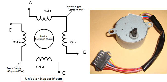
Stepper motors used in 8051 microcontroller projects are of two types: Unipolar and Bipolar. Unipolar stepper motor generally has five or six wires, in which four wires are one end of four stator coils, and the other end of all four coils is tied together, which represents the fifth wire; this is called the common wire (common point). Generally, there are two common wires, formed by connecting one end of the two coils as shown stepper motor interfacing with 8051 diagram. Unipolar stepper motor is a very common and popular 8051 microcontroller stepper motor control because of its ease of use and simple driver circuit requirements
In a Bipolar stepper motor, just four wires come out from two sets of coils, which means there are no common wires.
Interfacing of Stepper Motor with 8051 Microcontroller: Drive Modes
A stepper motor is made up of a stator and a rotator. Stator represents the four electromagnet coils which remain stationary around the rotator, and rotator represents the permanent magnet which rotates. Whenever the coils are energised by applying the current, the electromagnetic field is created, resulting in the rotation of the rotator (permanent magnet). Coils should be energised in a particular sequence to make the rotator rotate. Based on this “sequence”, we can divide the working method of the Unipolar stepper motor into three modes: Wave drive mode, full step drive mode and half step drive mode. Each mode offers different advantages for stepper motor control using 8051 microcontroller project applications.
Wave Drive Mode for 8051 Stepper Motor Control
Wave drive mode: In this mode, one coil is energised at a time; all four coils are energised one after another. It produces less torque in comparison with full-step drive mode, but power consumption is lower. Following is the table for producing this mode using a microcontroller, which means we need to give Logic 1 to the coils in a sequential manner.
Wire identification process in steps:
1. Phase wire identification: There will be no resistance reading with the multimeter between wires of different phases.
2. Common wire identification: The common wire and other coil wires in the same phase should yield the same resistance.
3. Coil endpoints confirmation: The two endpoints of coils in the same phase will yield 2 x the resistance to the resistance between the common point and one endpoint.
This wire identification process is important to properly define the stepper motor with the 8051 microcontroller working principle. Wiring the coils incorrectly would cause the motor to vibrate instead of rotating smoothing.
Steps | A | B | C | D |
1 | 1 | 0 | 0 | 0 |
2 | 0 | 1 | 0 | 0 |
3 | 0 | 0 | 1 | 0 |
4 | 0 | 0 | 0 | 1 |
Full Step Drive Mode Programming
Full Drive mode: In this, two coils are energised at the same time, producing high torque. Power consumption is higher. We need to give Logic 1 to two coils at the same time, then to the next two coils and so on.
Steps | A | B | C | D |
1 | 1 | 1 | 0 | 0 |
2 | 0 | 1 | 1 | 0 |
3 | 0 | 0 | 1 | 1 |
4 | 1 | 0 | 0 | 1 |
Half-Step Drive Mode Implementation
Half Drive mode: In this mode, one and two coils are energised alternatively, which means firstly one coil is energised, then two coils are energised, then again one coil is energised, then again two, and so on. This is a combination of full and wave drive modes, and is used to increase the angular rotation of the motor.
Steps | A | B | C | D |
1 | 1 | 0 | 0 | 0 |
2 | 1 | 1 | 0 | 0 |
3 | 0 | 1 | 0 | 0 |
4 | 0 | 1 | 1 | 0 |
5 | 0 | 0 | 1 | 0 |
6 | 0 | 0 | 1 | 1 |
7 | 0 | 0 | 0 | 1 |
8 | 1 | 0 | 0 | 1 |
Stepper Motor Interfacing with 8051 Diagram and Circuit Connection
Interfacing of stepper motor with 8051 microcontroller is very easy; we just need to give the 0 and 1 to the four wires of the stepper motor according to the above table, depending on which mode we want to run the stepper motor. And remaining two wires should be connected to a proper 12V supply (depending on the stepper motor). Here we have used the unipolar stepper motor. We have connected the four ends of the coils to the first four pins of port 2 of the 8051 through the ULN2003A.

ULN2003A Driver IC for Stepper Motor Control
8051 doesn’t provide enough current to drive the coils, so we need to use a current driver IC that is ULN2003A. ULN2003A is an array of seven NPN Darlington transistor pairs. The Darlington pair is constructed by connecting two bipolar transistors to achieve high current amplification. In ULN2003A, 7 pins are input pins and 7 pins are output pins, two pins are for Vcc (power supply) and Ground. Here we are using four input and four output pins. We can also use the L293D IC in place of the ULN2003A for current amplification.
Wire Identification for 8051 Stepper Motor Interface
You need to find out four coil wires and two common wires very carefully, otherwise the motor will not rotate. You can find out by measuring resistance using a multimeter; the multimeter won’t show any readings between the wires of the two phases. The common wire and the other two wires in the same phase should show the same resistance, and the two end points of the two coils in the same phase will show twice the resistance compared with the resistance between the common point and one end point.
Troubleshooting Stepper Motor with 8051 Interface
If your motor is not rotating OR vibrating but not rotating, then you must check the following checklist:
- First, check the circuit connections and code.
- If the circuit and code are ok, then check that the stepper motor gets a proper supply voltage (generally 12V), otherwise it just vibrates but does not rotate.
- If supply is fine, then check the four coil end points which in connected to ULN2003A. First, find the two common end points and connect them to 12V, then connect the remaining four wires to ULN2003A and try every possible combination until the motor gets started. If you don’t connect them in the proper order, then the motor just vibrates instead of rotating.
Here is the code for Wave step mode and full wave step mode. You can easily calculate the value for PORT P2 for the half-wave mode.
Technical Summary and GitHub Repository
This project provides a technical overview with a focus on its core architecture, system components, and implementation specifics. Highlighted are the main functionalities, requirements (hardware/software), and workflow. You can view the entire source code and documentation within the repository located on GitHub.


Commonly Asked Questions on Stepper Motor Interfacing with 8051
⇥ What is the difference between unipolar and bipolar stepper motors in terms of interfacing with the 8051?
Unipolar stepper motors have either 5 or 6 wires with common wires, as well as controlling circuits that are easy to interface with the 8051 using basic driver ICs such as the ULN2003A. Bipolar stepper motors have 4 wires and are able to provide more torque than unipolar motors. Nonetheless, they use a more complex driver circuit like the L293D.
⇥ Why do I need the ULN2003A driver IC for a stepper motor with the 8051?
The output pins on the 8051 microcontroller will only output 1-2mA of current, which isn't enough to activate the coils of a stepper motor (typically requiring 100 - 500mA). The ULN2003A stakeholder will perform current amplification and comes with integrated circuits that can protect against high voltage levels.
⇥ What causes my stepper motor to vibrate and not rotate with 8051?
Possible causes include wrong wire connections on the computer, not enough voltage in the power supply, incorrect coding / wrong stepping sequence in the code, or the driver IC not functioning or being defective. Make sure the power supply has sufficient voltage, typically 12V, check all the wire connections, especially if there is an interruption in the code, and make sure there is enough space between code interrupt timings.
⇥ Which drive mode is best for controlling a stepper motor with the 8051?
Full step mode gives maximum torque, wave drive gives the lowest power consumption, and half step gives the highest resolution. Select based on the needs of the application for torque, consumption, and precision.
Related Stepper Motor Control Projects Across Platforms
Develop a deeper understanding of stepper motor control by exploring how various microcontroller platforms handle motor interfacing.

Interfacing Stepper Motor with AVR Microcontroller Atmega16
In this tutorial we will interface 28BYJ-48 Stepper Motor with Atmega16 AVR Microcontroller using Atmel Studio 7.0. We will be interfacing the stepper motor with both the motor drivers ULN2003 and L293D.

Interfacing Stepper Motor with ARM7-LPC2148
In this tutorial we will see how to interface Stepper Motor with ARM7-LPC2148 and how to control speed of it.

Stepper Motor Control with A4988 Stepper Motor Driver and Arduino UNO
In this project, we will learn how we can control the stepper motor using A4988 Stepper Motor Driver Module. For this, we will interface A4988 Stepper Motor Driver Module with Arduino.
Complete Project Code
// Wave drive Mode
#include<reg51.h>
void msdelay(unsigned int time)
    {
        unsigned i,j ;
        for(i=0;i<time;i++)
        for(j=0;j<1275;j++);
    }
void main()
{
    while(1)
    {
        P2=0x01;            // 0001 P2_0=1,P2_1=0,P2_2=0,P2_3=0
        msdelay(1);
        P2=0x02;           //0010
        msdelay(1);
        P2=0x04;           //0100
        msdelay(1);
        P2=0x08;           //1000
        msdelay(1);
    }
}
// Full drive Mode
#include<reg51.h>
void msdelay(unsigned int time)
    {
    unsigned i,j ;
    for(i=0;i<time;i++)
    for(j=0;j<1275;j++);
    }
void main()
{
    while(1)
    {
         P2 = 0x03;     //0011     P2_0=1,P2_1=1,P2_2=0,P2_3=0
        msdelay(1);
        P2 = 0x06;         //0110
        msdelay(1);
        P2 = 0x0C;         //1100
        msdelay(1);
        P2 = 0x09;         //1001
        msdelay(1);
    }
}

It is useful project