A stepper motor is a type of brushless DC motor that divides a full rotation into several steps, thus allowing for precise control of the motor's position. The A4988 stepper motor driver is a versatile stepper driver for controlling stepper motors for various applications. When combined with an Arduino UNO microcontroller, the A4988 stepper driver provides highly precise and efficient motor control capabilities. In this A4988 stepper motor driver tutorial, we'll be looking at how to interface and connect the A4988 stepper motor driver module Arduino and go over the basic principles of stepper motors, A4988 stepper motor driver pinout, wiring connections, and programming examples. Whatever you are building, whether it be a 3D printer, CNC machine, or robotics project, you will learn how to implement the A4988 stepper driver Arduino. We'll get into the details and implementation.
Stepper Motor Control with A4988 Driver and Arduino - Quick Overview
Build Time: 2-3 hours | Cost: $20-40 | Difficulty: Beginner
What You'll Learn: Stepper motor principles, A4988 driver setup, Arduino pin control, Microstepping configuration
Applications: 3D printers, CNC machines, Robotics projects, Automated positioning systems
Table of Contents
- Working
- Technical Specifications
- Complete Pin Configuration Guide
- A4988 Stepper Motor Driver Module Parts
- A4988 vs Popular Stepper Drivers
- Commonly Asked Questions
- Complete Circuit Diagram Analysis
- Step-by-Step Connection Guide
- Arduino Programming Code
- GitHub Repository
- Handling Errors in Interfacing
- Common Issues & Solutions
- Related Projects
How A4988 Stepper Motor Driver Module Works with Arduino
Stepper motors use a cogged wheel and electromagnets to rotate the wheel one ‘step’ at a time. Each HIGH pulse sent to the A4988 stepper driver energises the coil, attracting the teeth closest to the cogged wheel and driving the motor one step forward. This step-by-step motion is what makes the A4988 stepper motor driver Arduino combination ideal for applications requiring precise positioning control.
The A4988 stepper motor driver has an output drive capacity of up to 35V and ±2A. This allows you to control a bipolar stepper motor, such as the NEMA 17, at up to 2A output current per coil. The GIF above shows you how the motor works
A4988 Stepper Motor Driver Technical Specifications
Parameter | Specification | Notes |
|---|---|---|
Motor Supply Voltage (VMOT) | 8V to 35V | Higher voltage improves torque and speed |
Logic Supply Voltage (VDD) | 3.3V to 5.5V | Compatible with Arduino 3.3V and 5V |
Maximum Current per Coil | 2A | With adequate heat dissipation |
Microstepping Resolution | Full, 1/2, 1/4, 1/8, 1/16 | Controlled by MS1, MS2, MS3 pins |
Step Input Frequency | Up to 200kHz | Depends on supply voltage and load |
Operating Temperature | -20°C to +85°C | Industrial temperature range |
Package Type | 28-pin QFN | Compact surface mount package |
Built-in Protection | Overcurrent, Thermal | Automatic shutdown on fault conditions |
Current Regulation | Adjustable via potentiometer | VREF × 2.5 = Current Limit (A) |
Sleep Current | < 1mA | Ultra-low power sleep mode |
A4988 Stepper Motor Driver Pinout: Complete Pin Configuration Guide
Understanding the A4988 stepper motor driver pinout is crucial for successful Arduino integration. The A4988 stepper motor driver module has a total of 16 pins that connect to the stepper motor and the Arduino. The pinout is as follows

VDD This is the power pin of the Module; the VDD pin powers the internal logic circuit of the A4988 stepper driver. That can range from 3.3V to 5.5V. It's pin 10 of the module.
GND Ground connections are essential for proper A4988 stepper motor driver Arduino operation. The A4988 module has two ground pins(9,16).
VMOTMotor Supply pin gives power to the motor, which can range from 8V to 35V. According to the A4988 stepper motor driver datasheet, the motor driver requires a suitable decoupling capacitor close to the board.
Microstepping Control Pins
MS1, MS2, MS3.These microstepping resolution select pins are key features of the A4988 stepper motor driver module. The A4988 driver has three step size (resolution) selector inputs. By setting the appropriate logic levels for these pins, we can set the motor to one of five step resolutions.
MS1 | MS2 | MS3 | Microstep Resolution |
Low | Low | Low | Full Step |
High | Low | Low | Half Step |
Low | High | Low | Quarter Step |
High | High | Low | Eighth Step |
High | High | High | Sixteenth Step |
As for the microstepping pins, these have internal pull-down resistors; this means you can leave these pins disconnected, and the A4988 stepper driver reference will be configured into full-step mode by default.
Control Signal Pins
STEP input controls the microsteps of the motor. Each HIGH pulse sent to this pin drives the motor according to the number of microsteps determined by the microstep selection pins. The higher the pulse frequency, the faster the motor will spin.
DIR input controls the spinning direction of the motor. Pulling it HIGH turns the motor clockwise, while pulling it LOW turns it counterclockwise. Since higher pulse frequency results in faster movement of the motor, this pin is very important for speed control of the A4988 stepper motor driver Arduino. Digital control is basic, and this makes the combination of the A4988 stepper driver Arduino ideal for any bidirectional applications.
Enable and Control Pins
EN is an active low-input pin. When pulled LOW (default state), the A4988 stepper motor driver operates normally. By default, this pin is pulled low, so unless you pull it high, the driver is always enabled. This pin is particularly useful when implementing an emergency stop or shutdown system.
SLP is an active low-input pin. Pulling this pin LOW puts the driver into sleep mode, reducing power consumption to a minimum. You can use this to save power, especially when the motor is not in use.
RST is an active low input as well. When this pin is pulled LOW, all STEP inputs are ignored. Reset ignores all STEP inputs, which is very useful in A4988 stepper motor driver tutorial applications when completing homing sequences. The home state is the initial position from which the motor starts, and it varies based on microstep resolution.
Motor Output Pins
1B, 1A, 2A, 2B The output channels of the A4988 motor driver are broken out to the side of the module with pins. The A4988 stepper motor driver module can supply up to 2A per coil, so it will work acceptably for NEMA 17 and similar stepper motors. However, the amount of current supplied to the motor is determined by the power supply, cooling system, and current limiting setting of the system.
A4988 Stepper Motor Driver Module Parts
The A4988 Stepper Motor Driver is a low-cost cost high-power motor driver IC that can be used for many applications. The parts marking of the A4988 is shown below.

As you can see from the above image, the main component on the board is the A4988 stepper motor controller; other than that, there are two more significant parts on the board. The other components will be current sensing resistors, protection diodes, voltage regulators, and the current adjustment (the potentiometer must be connected properly to ensure the A4988 stepper driver Arduino operations).
A4988 vs Popular Stepper Drivers Comparison
Feature | A4988 | DRV8825 | TMC2208 | Best Use Case |
|---|---|---|---|---|
Max Voltage | 35V | 45V | 35V | DRV8825 for high voltage |
Max Current | 2A | 2.2A | 2A | DRV8825 for high current |
Microstepping | 1/16 | 1/32 | 1/256 | TMC2208 for precision |
Noise Level | Moderate | Moderate | Ultra Quiet | TMC2208 for quiet operation |
Price Range | $2-5 | $3-6 | $8-15 | A4988 for budget projects |
Arduino Compatibility | Excellent | Excellent | Good | A4988/DRV8825 for beginners |
Heat Generation | Moderate | Higher | Lower | TMC2208 for continuous operation |
Configuration | Pin-based | Pin-based | UART/Pin-based | A4988 for simple setup |
Commonly Asked Questions about A4988 Stepper Motor Driver
⇥ What is the specification of A4988?
The A4988 is a complete microstepping motor driver with a built-in translator for easy operation. It is designed to operate bipolar stepper motors in full-, half-, quarter-, eighth-, and sixteenth-step modes, with an output drive capacity of up to 35 V and ±2 A.
⇥ What is the difference between A4988 and DRV8825?
The DRV8825 has a higher maximum supply voltage than the A4988 (45 V vs 35 V), which means the DRV8825 can be used more safely at higher voltages and is less susceptible to damage from LC voltage spikes.
⇥ What is the current limit of A4988?
The A4988 driver IC has a maximum current rating of 2 A per coil, but the actual current you can deliver depends on how well you can keep the IC cool.
⇥ Why does A4988 need a capacitor?
There are two purposes of such a capacitor: first, it supplies power for short peaks in demand, effectively enabling the 12V power source to supply much more current for a short time than it can support over a long time, and so the driver has more stable power and works generally better.
⇥ How do you set the current limit on A4988?
The current limit on the A4988 can be set by adjusting the potentiometer while measuring the voltage between ground and where the wiper of the potentiometer connects to the board. The current limit is calculated using the formula Current Limit = VREF x 2.5. For example, to set a maximum current limit of 1A, you need to set VREF to approximately .4V. You should always set the limit with the motor connected. We also recommend using a multimeter, as it is easier to get accurate readings that way.
⇥ What capacitor is needed for A4988?
A4988 must have a 100µF electrolytic capacitor placed between VMOT and GND on the driver board. The capacitor does several things: It smooths the high-frequency noise from the power supply, reduces voltage spikes upon switching, and protects the driver from the back-EMF induced in the stepper motor coils.
A4988 Schematic: Complete Circuit Diagram Analysis
The A4988 schematic provides a look at the internal structure of this advanced stepper motor driver. This schematic contains current-limiting resistors, a few protection circuits, and logic level translation to the Arduino 5V logic levels. Understanding the schematic provides one-way insight into troubleshooting and advanced applications' performance.

The schematic diagram of the A4988 Stepper Driver module is shown above. The circuit is very simple and can be found in the datasheet of the A4899 module. But for the sake of simplicity, we will go through the circuit diagram and will try to figure out the most critical parts that need special attention.
A4988 Stepper Driver Arduino Wiring: Step-by-Step Connection Guide
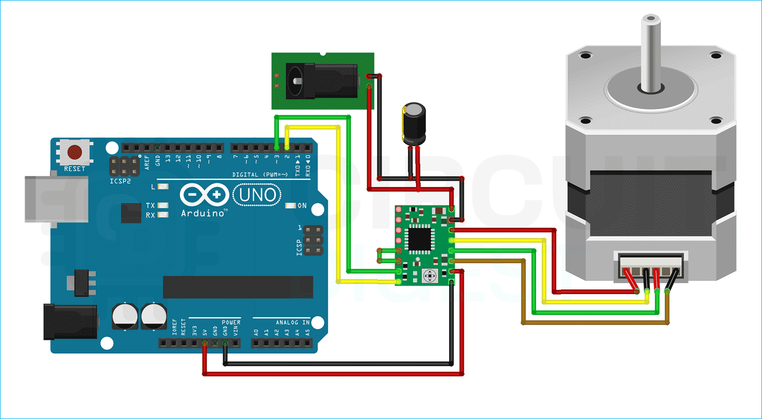
The schematic diagram of the A4988 motor driver Module interfacing with Arduino is shown below. The schematic diagram is very simple and requires very few components to work with. This is a wiring diagram that shows a complete A4988 stepper motor driver connected to an Arduino. The circuit demonstrates proper connections to the power supply, routing of the control signals, and the wiring of the stepper motor for optimal performance.
To power the logical part of the module, we will be using a lab bench power supply, and we will write the code so that the shaft of the motor will be moving back and forth, so that we can see the working of the motor driver in action. In the image below, we have shown you the hardware circuit of the motor driver.
Wiring Instructions:-
∗ Power Connections: VDD to Arduino 5V, both GND pins to Arduino ground, and VMOT to an external supply of 12V.
∗ Control Signals: Connect the STEP pin to digital pin 3 on Arduino, DIR pin to digital pin 2.
∗ Motor Connections: Wire the stepper motor coils to 1A, 1B, 2A, 2B pins according to motor specifications.
∗ Safety components: Add a 100µF capacitor between VMOT and GND to prevent voltage spikes.
If you are interested in other stepper motors, including 28-BYJ48, then check our previous articles on their operation with different microcontrollers:
- Interfacing Stepper Motor with Arduino Uno
- Interfacing Stepper Motor with STM32F103C8
- Interfacing Stepper Motor with PIC Microcontroller
- Interfacing Stepper Motor with MSP430G2
- Stepper Motor Interfacing with 8051 Microcontroller
- Stepper Motor Control with Raspberry Pi
A4988 Stepper Motor Driver Tutorial: Arduino Programming Code
This practical A4988 stepper motor driver tutorial demonstrates how to program Arduino for precise stepper motor control. The code example shows direction control, speed adjustment, and step counting for the A4988 stepper driver Arduino combination.
The code gets started by identifying the Arduino pins that are used to link the STEP and DIR pins of the A4988. StepsPerRevolution is a variable that is also defined. You may adjust it to your stepper motor's specifications.
const int dirPin = 2;
const int stepPin = 3;
const int stepsPerRevopinMode(stepPin, OUTPUT);
pinMode(dirPin, OUTPUT);
In the setup section, all motor control pins are configured as digital OUTPUT.
pinMode(stepPin, OUTPUT);
pinMode(dirPin, OUTPUT);
In the loop section, the motor is rotated slowly clockwise and then rapidly counterclockwise with one-second intervals.
The spinning direction of the motor is controlled by,
digitalWrite(dirPin, HIGH);The speed of the motor is controlled by the following code
for(int x = 0; x < stepsPerRevolution; x++) {
      digitalWrite(stepPin, HIGH);
      delayMicroseconds(1000);
      digitalWrite(stepPin, LOW);
      delayMicroseconds(1000);
}
This Arduino A4988 stepper motor driver code is about the most rudimentary motor control you can do. The shorter the delay, the faster the motor spins, making this code super useful for discovering some of the A4988 stepper driver concepts.
Technical Summary and GitHub Repository
The Technical Summary provided herein is meant to give a quick reference to the essential functionality of the project, including hardware, software, and design. It outlines some key functional features and operational ideas to help speed up the clarity of the overall project. The GitHub Repository will be updated with all source code, schematics, and documentation necessary to replicate and modify the project at your leisure.
Error in Interfacing A4988 4-Digit 7-Segment Display? - Here is what you should do
You see, Stepper Drivers provide current to each coil of a Stepper Motor and those currents are switched back and forth to make the Stepper Motor rotate. So when a connection to one of the coils gets disconnected, it creates a spike (current/voltage) that gets fed back to the Stepper Driver and can cause failure.
For the stepper motor to work properly, you need to connect a 100uF capacitor in parallel; otherwise, it can cause instability.
Common Issues & Solutions for A4988 Stepper Motor Driver
Power Supply Issues
» Low Current: Check the power supply to demonstrate the correct amount of current for your stepper motor specifications
» Voltage Spikes: Always place a 100μF capacitor on VMOT and GND of the A4988 stepper motor driver module
» Heat Build-up: Add heatsinks to the driver IC when using continuously or in high current applications, as the driver can run hot during use.
Troubleshooting Connection Issues
» Doesn't Move: Check the wiring connections/links, check the power supply, and check the wiring sequence for coils on the stepper motor if used to
» Erratic Movement: Check loose soldered connections, check electromagnetic interference, and check grounding.
» Overheating: Adjust the current limit potentiometer down and have proper cooling on the A4988 stepper driver Arduino project.
Projects Using Arduino and A4988 Stepper Motor Driver IC
Controlling NEMA 17 Stepper Motor with Arduino and A4988 Stepper Driver Module
If you are looking for a simple interfacing tutorial on the A4988 motor driver module and Arduino, this project is for you, because in this project, we not only interfaced the A4988 with Arduino we have also added an extra potentiometer to control the rotation of the stepper.
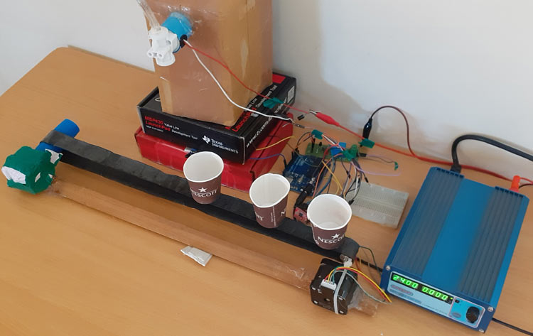
Automatic Bottle Filling System using Arduino
If you have some of these cheap stepper drivers lying around and you are thinking about building projects with them, then this project might be for you, because as the name of this project suggests, we have built an automatic bottle-filling system with them.
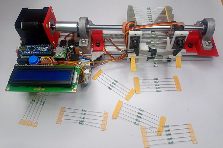
Arduino-Based Resistor Reel Cutting Machine
If you are looking for some really interesting projects to build and impress your friends, then this project is for you. In this project, we have made a resistor cutting machine that will make your life a lot easier.
Complete Project Code
// Define pin connections & motor steps per revolution
const int dirPin = 2;
const int stepPin = 3;
const int stepsPerRevolution = 200;
void setup() {
  // Declare pins as Outputs
  pinMode(stepPin, OUTPUT);
  pinMode(dirPin, OUTPUT);
}
void loop() {
  // Set motor direction clockwise
  digitalWrite(dirPin, HIGH);
  // Spin motor slowly
  for(int x = 0; x < stepsPerRevolution; x++) {
    digitalWrite(stepPin, HIGH);
    delayMicroseconds(2000);
    digitalWrite(stepPin, LOW);
    delayMicroseconds(2000);
  }
  delay(1000); // Wait a second
  // Set motor direction counterclockwise
  digitalWrite(dirPin, LOW);
  // Spin motor quickly
  for(int x = 0; x < stepsPerRevolution; x++) {
    digitalWrite(stepPin, HIGH);
    delayMicroseconds(1000);
    digitalWrite(stepPin, LOW);
    delayMicroseconds(1000);
  }
  delay(1000); // Wait a second
}


