
In this tutorial we will Interface Stepper Motor using MSP430. The MSP-EXP430G2 is a Development Tool a.k.a LaunchPad provided by the Texas Instruments to learn and practice on how to use their Microcontrollers. This board falls under the MSP430 Value Line category where we can program all the MSP430 series Microcontrollers. If you are new to MSP then check our getting started with MSP430 tutorial.
Stepper Motor:
Stepper Motor is a type of brushless DC Motor which converts electrical pulses into distinct mechanical movements. The shaft of a stepper motor rotates in discrete steps. We can get precise steps and speed according to our need.

We will use 35BYJ46 Bi-polar stepper motor which is cheaply available in the market. It has 6 wires but it comes with 5 wires also. There are 2 coils in our stepper motor. Each has 3 wires coming out of it. Out of 3 wires, 1 is centered tapped so, remaining 2 wires connected with coil directly. In total, we have 4 signal wires and 2 centered tapped wires which are connected with 5-12V power supply.
In case, if there are total 5 wires coming out of motor then 4 wires are signal wires and 1 is centered tapped to both coils. Like this.
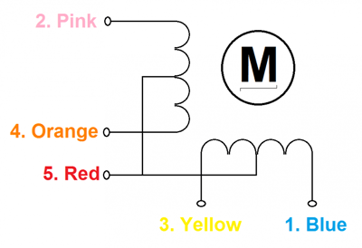
To check which wire is centered tapped or which is signal wire, you have to check resistance of wires coming out of the motor. So, those wires, which are connected with the same coil, has high resistance value as compared to resistance of centered tapped.
In above diagram, if we have checked resistance value of Blue and Yellow wires and resistance between them is more than the value between Yellow and Red or Blue and Red. So, Red is centered Tapped wire.
We have previously interfaced Stepper Motor with other Microcontrollers:
- Interfacing Stepper Motor with Arduino Uno
- Stepper Motor Control with Raspberry Pi
- Stepper Motor Interfacing with 8051 Microcontroller
- Interfacing Stepper Motor with PIC Microcontroller
Stepper motor can also be controlled without any Microcontroller, see this Stepper Motor Driver Circuit.
ULN2003 Stepper Motor Driver:
Most stepper motors will operate only with the help of a driver module. This is because the controller module (In our case MSP) will not be able to provide enough current from its I/O pins for the motor to operate. So we will use an external module like ULN2003 module as stepper motor driver. There are a many types of driver module and the rating of one will change based on the type of motor used. The primary principle for all driver modules will be to source/sink enough current for the motor to operate.
In this project, we will use ULN2003 motor driver IC. Pin diagram of IC is given below:
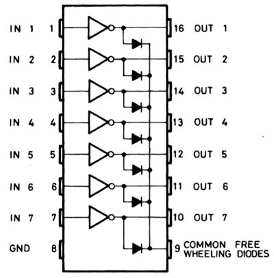
We will use 4 input and 4 output port if IC.
Materials Required:
- MSP430
- 35BYJ46 or 28-BYJ48 Stepper motor
- ULN2003 IC
- Wires
- Breadboard
Circuit Diagram:

In above diagram, RED wire of stepper is not connected with PIN5 of IC .It has to be connected with 5V. Color code of your Stepper motor may be different from the colors given in the circuit diagram. So, connect the wires after checking the correct signal wires.
We will write our code using Energia IDE. It is same as Arduino IDE and easy to use. Sample code for driving the stepper can also be found in example menu of Arduino IDE.
Code and Working Explanation:
Before we start programming with our MSP430, let us understand what should actually happen inside the program. We will be using 4-step sequence method so we will have four steps to perform for making one complete rotation. Consider A, B, C and D as four coils.
|
Step |
Pin Energized |
Coils Energized |
|
Step 1 |
6 and 7 |
A and B |
|
Step 2 |
7 and 8 |
B and C |
|
Step 3 |
8 and 9 |
C and D |
|
Step 4 |
9 and 6 |
D and A |
In this tutorial, we are going to write the MSP430 stepper motor code . The complete program can be found at the end of the tutorial few important lines are explained below.
The number of steps per revolution for our stepper motor was calculated to be 32; hence we enter that as shown in the line below
const int STEPS = 32;
Next you have to create instances in which we specify the pins to which we have connected the Stepper motor.
Stepper myStepper (STEPS, 6, 7, 8, 9);
Since we are using the Stepper library, we can set the speed of the motor using the below line. The speed can range between 0 to 200 for 35BYJ46 stepper motors.
Mystepper.setSpeed(200);
Now, to make the motor move one step we can use the following line.
myStepper.step(STEPS);
Since we have 32 steps and 64 as the gear ratio we need to move 2048 (32*64=2048), to make one complete rotation. Now, upload the below code and change the no. of steps according to your need.
This is how you can interface stepper motor with a PIC Microcontroller, now you can use your own creativity and find out applications for this. There are lots of projects out there which use a stepper motor.
Complete Project Code
#include <Stepper.h>
const int STEPS = 32;  // change this to fit the number of steps per revolution
// for your motor
// initialize the stepper library on pins 6 through 9 or you can use any pins on MSP430:
Stepper myStepper(STEPS, 6,7,8,9);
void setup() {
                               // set the speed at 200rpm or as you want:
  myStepper.setSpeed(200);
}
void loop() {
  myStepper.step(STEPS);
}
