

Stepper Motor is a specially designed motor which rotates in steps. Speed of stepper motor depends on the rate of electrical signal applied to it. Different patterns can control stepper motor’s direction and rotation type. Mainly two types of stepper motors are available, Unipolar and Bipolar. Unipolar is easier to operate, control and also easier to get. Here in this tutorial we are interfacing Stepper Motor with PIC Microcontroller PIC16F877A.
We are using 28BYJ-48 stepper motor for this project which is cheap and easily available. It is 5V DC unipolar stepper motor. We are also using a Module available with this motor which consist ULN2003 Stepper Motor Driver IC. ULN2003 is a Darlington pair array, which is useful to drive this motor, since PIC microcontroller couldn’t provide enough current to drive. ULN2003A is capable to drive 500mA of load with 600mA of peak current.
Stepper Motor:
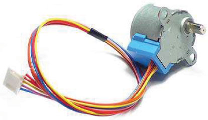
Let’s see the specification of the 28BYJ-48 Stepper Motor from the datasheet.

How to rotate Stepper Motor:
If we see the datasheet we will see the pin-out.
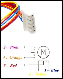
Inside the motor there are two center tapped coils available. Red wire is the common for both which will be connected at VCC or 5V.
Other 4 wires pink, red, yellow and blue will control the rotation depending on the electrical signal. Also, depending on the movement, this motor can be controlled using 3 steps. Full drive mode, Half Drive mode and Wave drive mode.
Three Driving Modes of Stepper Motor:
Full Drive: If two stator electromagnets are energized at a time, the motor will run at full torque referred as full-drive sequence mode.
|
Step |
Blue |
Pink |
Yellow |
Orange |
|
1 |
1 |
1 |
0 |
0 |
|
2 |
0 |
1 |
1 |
0 |
|
3 |
0 |
0 |
1 |
1 |
|
4 |
1 |
0 |
0 |
1 |
Half-Drive: When alternatively one and two phases are energized, the motor will run in half drive mode. It’s used to increase the angular resolution. Drawback is less torque produced in this movement.
|
Step |
Blue |
Pink |
Yellow |
Orange |
|
1 |
1 |
0 |
0 |
0 |
|
2 |
1 |
1 |
0 |
0 |
|
3 |
0 |
1 |
0 |
0 |
|
4 |
0 |
1 |
1 |
0 |
|
5 |
0 |
0 |
1 |
1 |
|
6 |
0 |
0 |
0 |
1 |
|
7 |
1 |
0 |
0 |
1 |
|
8 |
1 |
0 |
0 |
0 |
Wave Drive: In this mode, one stator electromagnet is turned on. Its follows 4 steps same as Full-drive mode. It consumes low power with low torque.
|
Step |
Blue |
Pink |
Yellow |
Orange |
|
1 |
1 |
0 |
0 |
0 |
|
2 |
0 |
1 |
0 |
0 |
|
3 |
0 |
0 |
1 |
0 |
|
4 |
0 |
0 |
0 |
1 |
We have previously interfaced Stepper Motor with other Microcontrollers:
- Interfacing Stepper Motor with Arduino Uno
- Stepper Motor Control with Raspberry Pi
- Stepper Motor Interfacing with 8051 Microcontroller
Stepper motor can also be controlled without any Microcontroller, see this Stepper Motor Driver Circuit.
ULN2003 Stepper Motor Driver:
Let’s understand the break out board which consist ULN2003 IC. It’s important to understand the pin out.
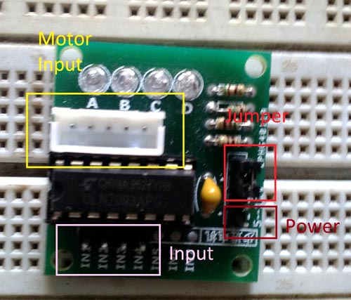
The yellow portion is used to connect the motor, The Red portion is showing a jumper, It’s important to place the jumper as it will enable freewheeling diode protection for the motor. The pink input is for the microcontroller connection.
We will rotate the motor in full drive mode in clock wise direction and again rotate it with wave drive mode in anti-clockwise direction. Check the demonstration Video at the end.
Required Components
- Pic16F877A
- Programming kit
- Breadboard
- 20Mhz Crystal
- 33pF disc capacitor – 2pcs
- 4.7k resistor
- Berg wires and pins
- ULN2003A breakout board along with the 28BYJ-48 Stepper motor.
- Additional wires to connect
- 5V power supply unit or wall adapter with 500mA rating
Circuit Diagram and Explanation

In the circuit diagram, on the left side the PIC16F877A is showing and on the right side the ULN2003A connection is showing. The ULN2003 and the Stepper motor part is inside the breakout board.
The Connection from Breakout board to the microcontroller unit will be-
A.IN1 => Pin33
B.IN2 => Pin34
C.IN3 => Pin35
D.IN4 => Pin36
I connected all the components and your hardware to rotate Stepper motor with PIC microcontroller is ready.
If you are new to PIC Microcontroller than follow our PIC Microcontroller Tutorials stating with Getting started with PIC Microcontroller.
Code Explanation
Full code for this PIC based Stepper Motor Driver is given at the end of this tutorial with a Demonstration Video. As always first, we need to set the configuration bits in the pic microcontroller and then start with void main function.
These are the macros for configuration bits of the microcontroller unit and the library header files.
#define _XTAL_FREQ 200000000 //Crystal Frequency, used in delay
#define speed 1 // Speed Range 10 to 1  10 = lowest , 1 = highest
#define steps 250 // how much step it will take
#define clockwise 0 // clockwise direction macro
#define anti_clockwise 1 // anti clockwise direction macro
In the first line we defined crystal frequency which is needed for the delay routine. Other macros are used to define user related options.
If you see the code, there are three functions defined for driving the motor in three modes with clock-wise and anti-clockwise direction. Here are the three functions:
1.void full_drive (char direction)
2.void half_drive (char direction)
3.void wave_drive (char direction)
Check the definitions of these functions in the complete code given below:
Now in void main function, we are driving the motor clockwise using full-drive mode depending on the steps and after few seconds delay we again rotate the motor anti-clockwise using wave drive mode.
void main(void)
{
system_init();
while(1){
/* Drive the motor in full drive mode clockwise */
for(int i=0;i<steps;i++)
{
full_drive(clockwise);
}
ms_delay(1000);
/* Drive the motor in wave drive mode anti-clockwise */
for(int i=0;i<steps;i++)
{
wave_drive(anti_clockwise);
//full_drive(anti_clockwise);
}
ms_delay(1000);
}
}
This is how we can rotate the stepper motor with PIC Microcontroller. Stepper Motors are very useful in CNC machines, robotics and other embedded applications.
Complete Project Code
/*
 * File:   main.c
 * Author: Sourav Gupta
 * By:- circuitdigest.com
 * Created on May 10, 2018, 1:26 PM
 * This program will drive a servo motor.
 */

// PIC16F877A Configuration Bit Settings

// 'C' source line config statements

// CONFIG
#pragma config FOSC = HS        // Oscillator Selection bits (HS oscillator)
#pragma config WDTE = OFF       // Watchdog Timer Enable bit (WDT disabled)
#pragma config PWRTE = OFF      // Power-up Timer Enable bit (PWRT disabled)
#pragma config BOREN = ON       // Brown-out Reset Enable bit (BOR enabled)
#pragma config LVP = OFF        // Low-Voltage (Single-Supply) In-Circuit Serial Programming Enable bit (RB3/PGM pin has PGM function; low-voltage programming enabled)
#pragma config CPD = OFF        // Data EEPROM Memory Code Protection bit (Data EEPROM code protection off)
#pragma config WRT = OFF        // Flash Program Memory Write Enable bits (Write protection off; all program memory may be written to by EECON control)
#pragma config CP = OFF         // Flash Program Memory Code Protection bit (Code protection off)


#include <xc.h>
#include <stdio.h>

/*
 Hardware related definition
 */

#define _XTAL_FREQ 200000000 //Crystal Frequency, used in delay
#define speed 1 // Speed Range 10 to 1  10 = lowest , 1 = highest
#define steps 250 // how much step it will take
#define clockwise 0 // clockwise direction macro
#define anti_clockwise 1 // anti clockwise direction macro


/*
 *Application related function and definition
 */

void system_init (void); // This function will initialise the ports.
void full_drive (char direction); // This function will drive the motor in full drive mode
void half_drive (char direction); // This function will drive the motor in full drive mode
void wave_drive (char direction); // This function will drive the motor in full drive mode
void ms_delay(unsigned int val);

/*
 * main function starts here
 */


void main(void)
{
system_init();
while(1){
/* Drive the motor in full drive mode clockwise */
for(int i=0;i<steps;i++)
{
            full_drive(clockwise);
}

ms_delay(1000);

/* Drive the motor in wave drive mode anti-clockwise */
for(int i=0;i<steps;i++)
{
            wave_drive(anti_clockwise);
            //full_drive(anti_clockwise);
}
ms_delay(1000);
}
}

/*System Initialising function to set the pin direction Input or Output*/

void system_init (void){
    TRISB = 0x00;     // PORT B as output port
    PORTB = 0x0F;
}

/*This will drive the motor in full drive mode depending on the direction*/

void full_drive (char direction){
    if (direction == anti_clockwise){
        PORTB = 0b00000011;
        ms_delay(speed);
        PORTB = 0b00000110;
        ms_delay(speed);
        PORTB = 0b00001100;
        ms_delay(speed);
        PORTB = 0b00001001;
        ms_delay(speed);
        PORTB = 0b00000011;
        ms_delay(speed);
    }
    if (direction == clockwise){
        PORTB = 0b00001001;
        ms_delay(speed);
        PORTB = 0b00001100;
        ms_delay(speed);
        PORTB = 0b00000110;
        ms_delay(speed);
        PORTB = 0b00000011;
        ms_delay(speed);
        PORTB = 0b00001001;
        ms_delay(speed);
    }

}

/* This method will drive the motor in half-drive mode using direction input */

void half_drive (char direction){
    if (direction == anti_clockwise){
        PORTB = 0b00000001;
        ms_delay(speed);
        PORTB = 0b00000011;
        ms_delay(speed);
        PORTB = 0b00000010;
        ms_delay(speed);
        PORTB = 0b00000110;
        ms_delay(speed);
        PORTB = 0b00000100;
        ms_delay(speed);
        PORTB = 0b00001100;
        ms_delay(speed);
        PORTB = 0b00001000;
        ms_delay(speed);
        PORTB = 0b00001001;
        ms_delay(speed);
    }
    if (direction == clockwise){
       PORTB = 0b00001001;
       ms_delay(speed);
       PORTB = 0b00001000;
       ms_delay(speed);
       PORTB = 0b00001100;
       ms_delay(speed);
       PORTB = 0b00000100;
       ms_delay(speed);
       PORTB = 0b00000110;
       ms_delay(speed);
       PORTB = 0b00000010;
       ms_delay(speed);
       PORTB = 0b00000011;
       ms_delay(speed);
       PORTB = 0b00000001;
       ms_delay(speed);
    }
}

/* This function will drive the the motor in wave drive mode with direction input*/

void wave_drive (char direction){
    if (direction == anti_clockwise){
        PORTB = 0b00000001;
        ms_delay(speed);
        PORTB = 0b00000010;
        ms_delay(speed);
        PORTB = 0b00000100;
        ms_delay(speed);
        PORTB = 0b00001000;
        ms_delay(speed);
    }
     if (direction == clockwise){
        PORTB = 0b00001000;
        ms_delay(speed);
        PORTB = 0b00000100;
        ms_delay(speed);
        PORTB = 0b00000010;
        ms_delay(speed);
        PORTB = 0b00000001;
        ms_delay(speed);
    }

}

/*This method will create required delay*/

void ms_delay(unsigned int val)
{
     unsigned int i,j;
        for(i=0;i<val;i++)
            for(j=0;j<1650;j++);
}

hi sir
how to control clock pulse in pic16f690
I used to say that the variable has been used as a clock ,
clock 0v-188us and 5v- 18.8us means one clock cycle time 0v-188us and 5v-18.8us how to write code ??