

Raspberry Pi is an ARM architecture processor based board designed for electronic engineers and hobbyists. The PI is one of most trusted project development platforms out there now. With higher processor speed and 1 GB RAM, the PI can be used for many high profile projects like Image processing and Internet of Things.
For doing any of high profile projects, one need to understand the basic functions of PI. We will be covering all the basic functionalities of Raspberry Pi in these tutorials. In each tutorial we will discuss one of functions of PI. By the end of this Raspberry Pi Tutorial Series, you will be able to do high profile projects by yourself. Go through below tutorials:
- Getting Started with Raspberry Pi
- Raspberry Pi Configuration
- LED Blinky
- Raspberry Pi Button Interfacing
- Raspberry Pi PWM generation
- Controlling DC Motor using Raspberry Pi
In this tutorial, we will Control the Speed of a Stepper Motor using Raspberry Pi. In Stepper Motor, as the name itself says, the rotation of shaft is in Step form. There are different types of Stepper Motor; in here we will be using the most popular one that is Unipolar Stepper Motor. Unlike DC motor, we can rotate stepper motor to any particular angle by giving it proper instructions.
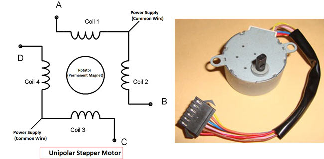
To rotate this Four Stage Stepper Motor, we will deliver power pulses by using Stepper Motor Driver Circuit. The driver circuit takes logic triggers from PI. If we control the logic triggers, we control the power pulses and hence the speed of stepper motor.
There are 40 GPIO output pins in Raspberry Pi 2. But out of 40, only 26 GPIO pins (GPIO2 to GPIO27) can be programmed. Some of these pins perform some special functions. With special GPIO put aside, we have only 17 GPIO remaining. Each of these 17 GPIO pin can deliver a maximum of 15mA current. And the sum of currents from all GPIO Pins cannot exceed 50mA. To know more about GPIO pins, go through: LED Blinking with Raspberry Pi
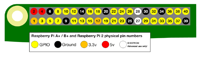
There are +5V (Pin 2 & 4) and +3.3V (Pin 1 & 17) power output pins on the board for connecting other modules and sensors. These power rails cannot be used to drive the Stepper Motor, because we need more power to rotate it. So we have to deliver the power to Stepper Motor from another power source. My stepper motor has a voltage rating of 9V so I am using a 9v battery as my second power source. Search your stepper motor model number to know voltage rating. Depending on the rating choose the secondary source appropriately.
As stated earlier, we need a driver circuit to drive the Stepper Motor. We will also be designing a Simple Transistor Driver Circuit here.
Components Required:
Here we are using Raspberry Pi 2 Model B with Raspbian Jessie OS. All the basic Hardware and Software requirements are previously discussed, you can look it up in the Raspberry Pi Introduction, other than that we need:
- Connecting pins
- 220Ω or 1KΩresistor (3)
- Stepper Motor
- Buttons (2)
- 2N2222 Transistor (4)
- 1N4007 Diode (4)
- Capacitor- 1000uF
- Bread Board
Circuit Explanation:

Stepper motor use 200 steps to complete 360 degree rotation, means its rotate 1.8 degree per step. As we are driving a Four Stage Stepper Motor, so we need to give four pulses to complete single logic cycle. Each step of this motor completes 1.8 degree of rotation, so in order to complete a cycle we need 200 pulses. So 200/4 = 50 logic cycles needed to complete a single rotation. Check this to know more about Steppers Motors and its Driving Modes.
We will be driving each of these four coils by a NPN transistor (2N2222), this NPN transistor takes the logic pulse from PI and drives the corresponding coil. Four transistors are taking four logics from PI to drive four stages of stepper motor.
The transistor driver circuit is a tricky setup; here we should pay attention that wrongly connecting the transistor might load the board heavily and damage it. Check this to properly understand the Stepper Motor Driver Circuit.
The motor is an induction and so while switching the motor, we experience inductive spiking. This spiking will heat up the transistor heavily, so we will be using Diode (1N4007) to provide protection to transistor against Inductive Spiking.
In order to reduce the voltage fluctuations, we will be connecting a 1000uF capacitor across the power supply as shown in the Circuit Diagram.
Working Explanation:
Once everything is connected as per the circuit diagram, we can turn ON the PI to write the program in PYHTON.
We will talk about few commands which we are going to use in PYHTON program,
We are going to import GPIO file from library, below function enables us to program GPIO pins of PI. We are also renaming “GPIO” to “IO”, so in the program whenever we want to refer to GPIO pins we will use the word ‘IO’.
import RPi.GPIO as IO
Sometimes, when the GPIO pins, which we are trying to use, might be doing some other functions. In that case, we will receive warnings while executing the program. Below command tells the PI to ignore the warnings and proceed with the program.
IO.setwarnings(False)
We can refer the GPIO pins of PI, either by pin number on board or by their function number. Like ‘PIN 35’ on the board is ‘GPIO19’. So we tell here either we are going to represent the pin here by ‘35’ or ‘19’.
IO.setmode (IO.BCM)
We are setting four of GPIO pins as output for driving four coils of stepper motor.
IO.setup(5,IO.OUT) IO.setup(17,IO.OUT) IO.setup(27,IO.OUT) IO.setup(22,IO.OUT)
We are setting GPIO26 and GPIO19 as input pins. We will detect button press by these pins.
IO.setup(19,IO.IN)
IO.setup(26,IO.IN)
In case the Condition in the braces is true, the statements inside the loop will be executed once. So if the GPIO pin 26 goes low, then the statements inside the IF loop will be executed once. If the GPIO pin 26 does not goes low, then the statements inside the IF loop will not be executed.
if(IO.input(26) == False):
This command executes the loop 100 times, x being incremented from 0 to 99.
for x in range (100):
While 1: is used for infinity loop. With this command the statements inside this loop will be executed continuously.
We have all the commands needed to achieve the Speed Control of Stepper Motor with this.
After writing the program and executing it, all there is left is operating the control. We have two buttons connected to PI. One for increments the delay between the four pulses and other for decrements the delay between the four pulses. The delay itself speaks of speed; if the delay is higher the motor takes brakes between each step and so rotation is slow. If the delay is near zero, then the motor rotates at maximum speed.
Here it should be remember that, there should be some delay between the pulses. After giving a pulse, stepper motor takes few milliseconds of time to reach its final stage. If there is no delay given between the pulses, the stepper motor will not move at all. Normally 50ms delay is fine between the pulses. For more accurate information, look into the data sheet.
So with two buttons we can control the delay, which in turns control the speed of the stepper motor.
Complete Project Code
import RPi.GPIO as IO         # we are calling for header file which helps us use GPIO’s of PI
import time                            # we are calling for time to provide delays in program
IO.setwarnings(False)           # do not show any warnings
x=1                                         # integer for storing the delay multiple
IO.setmode (IO.BCM)
IO.setup(5,IO.OUT)             # initialize GPIO5 as an output.
IO.setup(17,IO.OUT)
IO.setup(27,IO.OUT)
IO.setup(22,IO.OUT)
IO.setup(19,IO.IN)              # initialize GPIO19 as an input.
IO.setup(26,IO.IN)
while 1:                               # execute loop forever
    IO.output(5,1)                 # Step1 go high
    IO.output(22,0)
    for y in range(x):             # sleep for  x*100msec
        time.sleep(0.01)
    IO.output(17,1)               # step2 go high
    IO.output(5,0)
    for y in range(x):
        time.sleep(0.01)         # sleep for  x*100msec
    IO.output(27,1)              #step 3 go high
    IO.output(17,0)
    for y in range(x):
        time.sleep(0.01)         # sleep for  x*100msec
    IO.output(22,1)              #step 4 go high
    IO.output(27,0)
    for y in range(x):
        time.sleep(0.01)                           # sleep for  x*100msec
        if(IO.input(26) == False):            #if button1 is pressed
            if(x<100):
            x=x+1                                      #increment x by one if x<100
            time.sleep(0.5)                        #sleep for 500ms
        if(IO.input(19) == False):           #if button2 is pressed
            if(x>1):
            x=x-1                                       #decrement x by one if x>1
            time.sleep(0.5)                         #sleep for 500ms
Comments
I want to known Completely Circuit diagram of Raspberry Pi with 2N222 Transistor for Stepper motor
Wow - great tutorial for a down-and-dirty stepper controller.

I like it I need more information about it
all