

Raspberry Pi is a pocked sized computer which also have GPIO pins for connecting it to other sensors and peripherals which makes it a good platform for embedded engineers. It has an ARM architecture processor based board designed for electronic engineers and hobbyists. The PI is one of most trusted project development platforms out there now. With higher processor speed and high RAM, the Raspberry Pi can be used for many high profile projects like Image processing and Internet of Things. Raspberry Pi 4 with 8GB RAM is the high end version available for sale now. It also has other lower version with 4GB and 2GB RAM.
For doing any of high profile projects, one need to understand the basic functions of PI. That is why we are here, we will be teaching all the basic functionalities of Raspberry Pi in these tutorials. In each tutorial series we will discuss one of functions of PI. By the end of tutorial series you will be able to do high profile projects by yourself. Check these for Getting Started with Raspberry Pi and Raspberry Pi Configuration.
In this tutorial of PI series, we will understand the concept of writing and executing programs on PYTHON. We will start with Blink LED using Raspberry Pi. Raspberry Pi LED Blink is done by connecting an LED to one of GPIO pins of PI and turning it ON and OFF. After learning the basics of Raspberry Pi, you can move on its high end applications, which we have covered in our dedicated Raspberry Pi section and can also check basics by following interfacing a button with Raspberry Pi, Raspberry Pi PWM tutorial, using DC motor with Raspberry Pi etc.
We will discuss a bit about PI GPIO Pins before going any further,
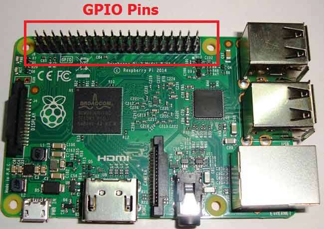
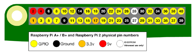
As shown in above figure, there are 40output pins for the PI. But when you look at the second figure, you can see not all 40 pin out can be programmed to our use. These are only 26 GPIO pins which can be programmed. These pins go from GPIO2 to GPIO27.
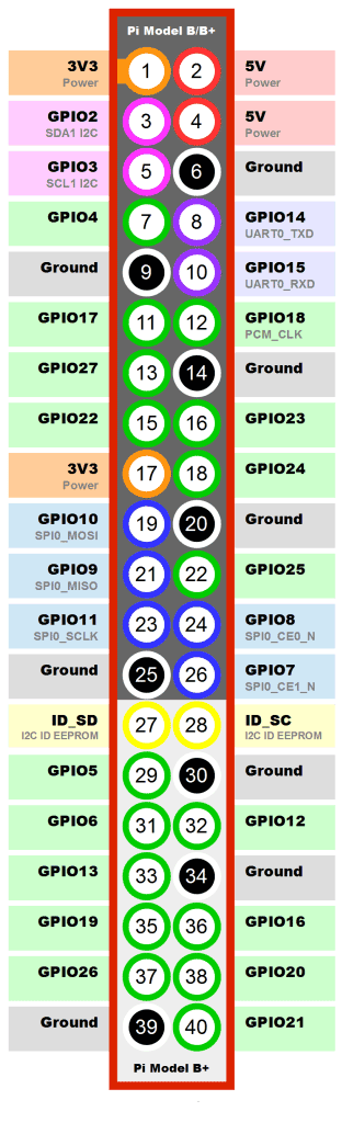
These 26 GPIO pins can be programmed as per need. Some of these pins also perform some special functions, we will discuss about that later. With special GPIO put aside, we have 17 GPIO remaining (Light green Cirl).
Each of these 17 GPIO pins can deliver a maximum of 15mA current. And the sum of currents from all GPIO cannot exceed 50mA. So we can draw a maximum of 3mA in average from each of these GPIO pins. So one should not tamper with these things unless you know what you are doing.
Components Required
Here we are using Raspberry Pi 2 Model B with Raspbian Jessie OS. All the basic Hardware and Software requirements are previously discussed, you can look it up in the Raspberry Pi Introduction, other than that we need:
- Connecting pins
- 220Ω or 1KΩresistor
- LED
- Bread Board
Circuit Explanation:
Circuit diagram for Raspberry Pi LED Blink is given below:

As shown in the circuit diagram we are going to connect an LED between PIN40 (GPIO21) and PIN39 (GROUND). As said earlier, we cannot draw more than 15mA from any one of these pins, so to limit the current we are connecting a 220Ω or 1KΩ resistor in series with the LED.
Working Explanation:
Since we have everything ready, turn ON your PI and go to the desktop.
1. On the desktop, go the Start Menu and choose for the PYTHON 3, as shown in figure below.
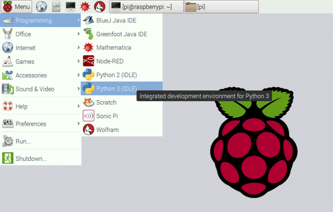
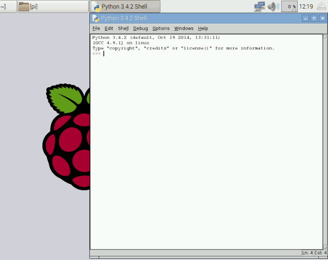
2. After that, PYHON will run and you will see a window as shown in below figure.
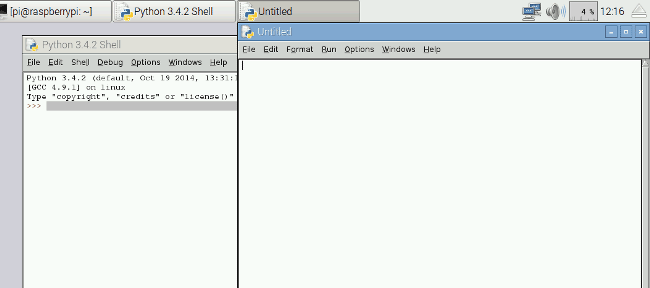
3. After that, click on New File in File Menu, You will see a new Window open,
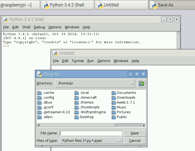
4. Save this file as blinky on the desktop,
5. After that write the program for blinky as given below and execute the program by clicking on “RUN” on ‘DEBUG’ option.
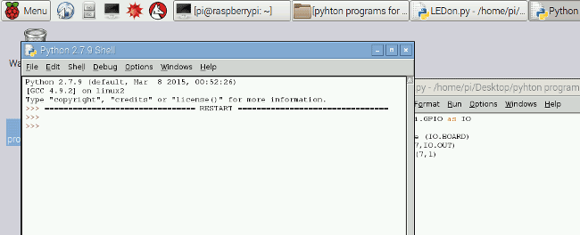
If the program has no errors in it, you will see a “>>>”, which means the program is executed successfully. By this time you should see the LED blinking three times. If there were any errors in the program, the execution tells to correct it. Once the error is corrected execute the program again.
Complete PYTHON program Code for LED Blinking is given below.
Complete Project Code
import RPi.GPIO as IO            # calling header file for GPIO’s of PI
import time                              # calling for time to provide delays in program
IO.setmode (IO.BOARD)       # programming the GPIO by BOARD pin numbers, GPIO21 is called as PIN40
IO.setup(40,IO.OUT)             # initialize digital pin40 as an output.
IO.output(40,1)                      # turn the LED on (making the voltage level HIGH)
time.sleep(1)                         # sleep for a second
IO.cleanup()                         # turn the LED off (making all the output pins LOW)
time.sleep(1)                        #sleep for a second
#loop is executed second time
IO.setmode (IO.BOARD)
IO.setup(40,IO.OUT)
IO.output(40,1)
time.sleep(1)
IO.cleanup()
time.sleep(1)

#loop is executed third time
IO.setmode (IO.BOARD)
IO.setup(40,IO.OUT)
IO.output(40,1)
time.sleep(1)
IO.cleanup()
time.sleep(1)
Comments
Will, look at the next image (the vertical one). This shows the usable GPIO pins with a green circle around them.
I am using a raspberry pi zero W, I hooked up the led with a series 470 ohm resistor
connected to ground (pin#06) and GPIO21, type in the code per your instruction
using python 3, ran the program, and the led flashed three times, it all worked perfectly.
Thank you very much for your article, this is my first experience writing a program
using a raspberry pi. How do you write a program using python, so the program
will loop, for the led to flash continuously?
Very Good tutorial. I was able to do LED blinking with your code and instruction. Keep going and Thanks.
Hello,
I ran the code exactly as above but i got an error:
AttributeError: module 'RPi.GPIO' has no attribute 'Setup'
Please help
your code doesn't work!

is it me or those 17 light green gpio pins are acc yellow. someone pls confirm im not crazy