

Raspberry Pi is an ARM architecture processor based board designed for electronic engineers and hobbyists. The PI is one of most trusted project development platforms out there now. With higher processor speed and 1 GB RAM, the PI can be used for many high profile projects like Image processing and Internet of Things.
For doing any of high profile projects, one need to understand the basic functions of PI. That is why we are here, we will be covering all the basic functionalities of Raspberry Pi in these tutorials. In each tutorial series we will discuss one of functions of PI. By the end of tutorial series you will be able to do high profile projects by yourself. Check these for Getting Started with Raspberry Pi and Raspberry Pi Configuration.
Establishing communication between PI and user is very important for designing projects on PI. For the communication, PI must take Inputs from the user. In this second tutorial of PI series, we will Interface a button to Raspberry Pi, to take INPUTS from the user.
Here we will connect a button to one GPIO Pin and an LED to another GPIO pin of Raspberry Pi. We will write a program in PYTHON, to blink the LED continuously, on pressing the button by the user. LED will be blinking by turning the GPIO On and Off.
Before going for the programming, let’s talk a bit about the LINUX and PYHTON.
LINUX:
LINUX is an Operating System like Windows. It performs all the basic functions which Windows OS can do. The main difference between them is, Linux is open source software where Windows is not. What it basically means is, Linux is free while Windows is not. Linux OS can be downloaded and operated for free, but for downloading genuine Windows OS, you have to pay the money.
And another major difference between them is Linux OS can be ‘modified’ by tweaking into the code, but Windows OS cannot be modified, doing so will lead to legal complications. So anyone can take the Linux OS, and can modify it to his requirement in order to create his own OS. But we cannot do this in Windows, the Windows OS is provided with restrictions to stop you from editing OS.
Here we are talking about Linux because, JESSIE LITE (Raspberry Pi OS) is LINUX based OS, which we have installed in Raspberry Pi Introduction part. The PI OS is generated on the grounds of LINUX, so we have to know a bit about LINUX operating commands. We will discuss about these Linux commands in the following tutorials.
PYTHON:
Unlike LINUX, PYTHON is a programming language like C, C++, and JAVA etc. These languages are used to develop applications. Remember programming languages run on Operating System. You cannot run a programming language without an OS. So OS is independent while programming languages are dependent. You can run PYTHON, C, C++, and JAVA on both Linux and Windows.
Applications developed by these programming languages can be games, browsers, apps etc. We will use programming language PYTHON on our PI, to design projects and to manipulate the GPIO’s.
We will discuss a bit about PI GPIO before going any further,
GPIO Pins:
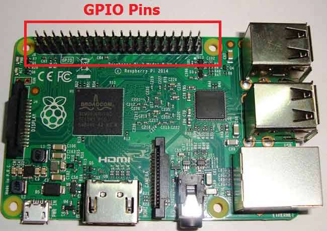
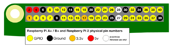
As shown in above figure, there are 40output pins for the PI. But when you look at the second figure, you can see not all 40 pin out can be programmed to our use. These are only 26 GPIO pins which can be programmed. These pins go from GPIO2 to GPIO27.
These 26 GPIO pins can be programmed as per need. Some of these pins also perform some special functions, we will discuss about that later. With special GPIO put aside, we have 17 GPIO remaining (Light green Cirl).
Each of these 17 GPIO pins can deliver a maximum of 15mA current. And the sum of currents from all GPIO cannot exceed 50mA. So we can draw a maximum of 3mA in average from each of these GPIO pins. So one should not tamper with these things unless you know what you are doing.
Components Required:
Here we are using Raspberry Pi 2 Model B with Raspbian Jessie OS. All the basic Hardware and Software requirements are previously discussed, you can look it up in the Raspberry Pi Introduction, other than that we need:
- Connecting pins
- 220Ω or 1KΩresistor
- LED
- Button
- Bread Board
Circuit Explanation:

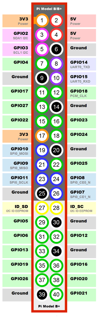
As shown in the circuit diagram we are going to connect an LED to PIN35 (GPIO19) and a button to PIN37 (GPIO26). As said earlier, we cannot draw more than 15mA from any one of these pins, so to limit the current we are connecting a 220Ω or 1KΩ resistor in series with the LED.
Working Explanation:
Once everything is connected, we can turn ON the Raspberry Pi to write the program in PYHTON and execute it. (To know how to use PYTHON go to PI BLINKY).
We will talk about few commands which we are going to use in PYHTON program.
We are going to import GPIO file from library, below function enables us to program GPIO pins of PI. We are also renaming “GPIO” to “IO”, so in the program whenever we want to refer to GPIO pins we will use the word ‘IO’.
import RPi.GPIO as IO
Sometimes, when the GPIO pins, which we are trying to use, might be doing some other functions. In that case, we will receive warnings while executing the program. Below command tells the PI to ignore the warnings and proceed with the program.
IO.setwarnings(False)
We can refer the GPIO pins of PI, either by pin number on board or by their function number. In pin diagram, you can see ‘PIN 37’ on the board is ‘GPIO26’. So we tell here either we are going to represent the pin here by ‘37’ or ‘26’.
IO.setmode (IO.BCM)
We are setting GPIO26 (or PIN37) as input pin. We will detect button press by this pin.
IO.setup(26,IO.IN)
While 1: is used for infinity loop. With this command the statements inside this loop will be executed continuously.
Once the program is executed, the LED connected to GPIO19 (PIN35) blinks whenever the button is pressed. Upon release the LED, it will go to OFF state again.
Complete Project Code
import RPi.GPIO as IO         #we are calling header file which helps us to use GPIO’s of PI
import time                           # we are calling for time to provide delays in program
IO.setwarnings(False)          #do not show any warnings
IO.setmode (IO.BCM)         #we are programming the GPIO by BCM pin numbers. (PIN39 as ‘GPIO19’)
IO.setup(19,IO.OUT)         # initialize GPIO19 as an output.
IO.setup(26,IO.IN)               #initialize GPIO26 as input
while 1:                                       #execute loop forever
    if(IO.input(26) == False):       #if GPIO26 goes low execute the below statements
          IO.output(19,True)           # turn the LED on (making the voltage level HIGH)
        time.sleep(0.11)                 #sleep for 100m second
        IO.output(19,False)            # turn the LED off (making GPIO19 low)
        time.sleep(1)                      #sleep for 100m second
