

Raspberry Pi is an ARM architecture processor-based board designed for electronic engineers and hobbyists. The PI is one of the most trusted project development platforms available today. With a higher processor speed and 1 GB of RAM, the PI can be used for many high-profile projects, such as image processing and the Internet of Things.
To do any of the high-profile projects, one needs to understand the basic functions of PI. We will be covering all the basic functionalities of Raspberry Pi in these tutorials. In each tutorial, we will discuss one of the functions of PI. By the end of the tutorial series, you will be able to do high-profile projects by yourself. Check these for Getting Started with Raspberry Pi and Raspberry Pi Configuration.
We have discussed the LED blinky and Button interface with the Raspberry Pi in previous tutorials. In this Raspberry Pi PWM tutorial, we will talk about getting Raspberry Pi PWM output. PWM stands for ‘Pulse Width Modulation’. PWM is a method used for getting a variable voltage out of a constant power supply. We will generate a pulse width modulation Raspberry Pi and demonstrate the PWM by varying the Brightness of an LED connected to the Pi.
Table of Contents
What is Pulse Width Modulation (PWM)?
We have previously talked about PWM many times in: Pulse width Modulation with ATmega32 , PWM with Arduino Uno, PWM with 555 timer IC and PWM with Arduino Due.
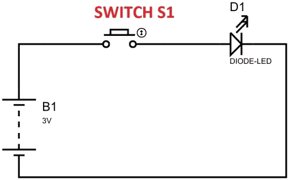
In the above figure, if the switch is closed continuously over a period of time, the LED will be ‘ON’ during this time. If the switch is closed for half a second and opened for the next half second, then the LED will be ON only in the first half second. Now the proportion for which the LED is ON over the total time is called the Duty Cycle, and can be calculated as follows:
Duty Cycle Calculation:
Duty Cycle =Turn ON time/ (Turn ON time + Turn OFF time)
Duty Cycle = (0.5/ (0.5+0.5)) = 50%
So the average output voltage will be 50% of the battery voltage.
How PWM Works - Quick Summary
| Parameter | Description | Formula |
| Duty Cycle | Percentage of time signal is HIGH | ON Time / (ON Time + OFF Time) × 100% |
| Frequency | Number of cycles per second | 1 / Period (Hz) |
| Average Voltage | Effective output voltage | Supply Voltage × Duty Cycle |
This is the case for one second, and we can see the LED being OFF for half a second and the LED being ON for the other half second. If the Frequency of ON and OFF times increased from ‘1 per second’ to ’50 per second’. The human eye cannot capture this frequency. For a normal eye, the LED will be seen as glowing with half of its brightness. So with further reduction of on-time, the LED appears much lighter.
We will program the PI to get a PWM and connect an LED to show its working.
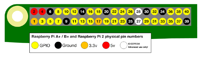
There are 40 GPIO output pins in the Raspberry Pi. But out of 40, only 26 GPIO pins (GPIO2 to GPIO27) can be programmed. TO know more about GPIO pins, go through: LED Blinking with Raspberry Pi
Pulse Width Modulation Raspberry Pi Pins Configuration
The pulse width modulation Raspberry Pi pins are specifically important for PWM applications.
| Pin Type | GPIO Number | Physical Pin | PWM Channel |
| Hardware PWM | GPIO18 | Pin 12 | PWM0 |
| Hardware PWM | GPIO19 | Pin 35 | PWM1 |
| Software PWM | Any GPIO | Any available | Software controlled |
Raspberry Pi PWM Basics
The Raspberry Pi has both hardware and software PWM. Knowing about PWM in Raspberry Pi is useful when it comes to driving devices such as arrays of LEDs, motors, and servos.
PWM Options on Raspberry Pi:
- Hardware PWM: Specific hardware pins with precise timing for PWM signals
- Software PWM: PWM signals that can be generated through software on any GPIO pin
Components Required for Pulse Width Modulation Raspberry Pi
Here we are using Raspberry Pi 2 Model B with Raspbian Jessie OS. All the basic Hardware and Software requirements have been previously discussed; you can look them up in the Raspberry Pi Introduction. Other than that, we need:
- Connecting pins
- 220Ω or 1KΩresistor
- LED
- Bread Board
Circuit Diagram Explanation

As shown in the circuit diagram, we are going to connect an LED between PIN35 (GPIO19) and PIN39 (ground). As said earlier, we cannot draw more than 15mA from any one of these pins, so to limit the current, we are connecting a 220Ω or 1KΩ resistor in series with the LED.
Working Explanation:
Once everything is connected, we can turn ON the Raspberry Pi to write the program in Python and execute it. Once everything is connected, we can power ON the Raspberry Pi to write the pulse width modulation Raspberry Pi Python program and execute it.
We will talk about a few commands which we are going to use in the Python program.
We are going to import the GPIO file from the library. The following function enables us to program the GPIO pins of the PI. We are also renaming “GPIO” to “IO”, so in the program, whenever we want to refer to GPIO pins, we will use the word ‘IO’.
import RPi.GPIO as IO
Sometimes, when the GPIO pins, which we are trying to use, might be doing some other functions. In that case, we will receive warnings while executing the program. The command below tells the PI to ignore the warnings and proceed with the program.
IO.setwarnings(False)
We can refer to the GPIO pins of PI, either by PIN on board or by their function number. In the pin diagram, you can see ‘PIN 35’ on the board is ‘GPIO19’. So here, either we are going to represent the pin here by ‘35’ or ‘19’.
IO.setmode (IO.BCM)
PWM Voltage Output Control
Understanding Raspberry Pi PWM voltage is essential for proper device control. We are setting GPIO19 (or PIN35) as an output pin. We will get PWM output from this pin.
IO.setup(19,IO.IN)
After setting the pin as an output, we need to set up the pin as a PWM output pin.
p = IO.PWM(output channel , frequency of PWM signal)
The above command is for setting up the channel and also for setting up the frequency of the PWM signal. ‘p’ here is a variable; it can be anything. We are using GPIO19 as the PWM output channel. The frequency of the PWM signal has been chosen to be 100, as we don’t want to see the LED blinking.
The command below is used to start PWM signal generation. ‘DUTYCYCLE’ is for setting the Turn On ratio, 0 means the LED will be ON for 0% of the time, 30 means the LED will be ON for 30% of the time, and 100 means completely ON.
p.start(DUTYCYCLE)
This command executes the loop 50 times, x being incremented from 0 to 49.
for x in range (50):
While 1: is used for an infinity loop. With this command, the statements inside this loop will be executed continuously.
With the program being executed, the duty cycle of the PWM signal increases. And then decreases after reaching 100%. With an LED attached to this PIN, the brightness of the LED increases first and then decreases.
Technical Summary and GitHub Repository
The Technical Summary offers a clear breakdown of the project’s design and functionality, while the GitHub Repository provides complete code and resources for seamless replication.


PWM Frequency Control
The pulse width modulation Raspberry Pi frequency is crucial for different applications.
| Application | Recommended Frequency | Reason |
| LED Dimming | 100Hz - 1kHz | Avoids visible flickering |
| Motor Control | 1kHz - 20kHz | Smooth operation, reduced noise |
| Servo Control | 50Hz | Standard servo frequency |
| Audio Applications | 20kHz+ | Above human hearing range |
PWM Applications and Projects
» Control LED Brightness: Variable lighting systems.
» Control Motor Speed: Adjustable DC motor speed.
» Control Servo Actuators: Precise angle positioning.
» Control Fan Speed: Cooling actuator, with temperature-triggered fan.
» Control RGB LEDs: RGB colour mixing and effects.
» Power Supply Control: Control of switching power supplies.
Frequently Asked Questions: Pulse Width Modulation Raspberry Pi
⇥ 1. What distinguishes hardware PWM from software PWM on the Raspberry Pi?
Hardware PWM uses dedicated timer hardware on GPIO18 and GPIO19 for high-accuracy timing and stable frequency generation. Software PWM may use any GPIO pin; that makes its timing dependent on CPU timing, and that means it is less accurate and is potentially affected by CPU load.
⇥ 2. Why is my PWM signal flickering or rough?
Flickering could be caused by a low PWM frequency, or for software PWM, CPU load, and/or an unstable power supply. You can switch to hardware PWM pins, bump the frequency below 1kHz, along with a stable power supply, to increase smoothness.
⇥ 3. What is the maximum current I can safely pull from the Raspberry Pi GPIO pins?
Each GPIO pin can deliver up to 16mA safely (keep in mind that you cannot draw over 50mA amongst all of the GPIO pins). Always use current-limiting resistors (typically between 220Ω and 1kΩ for LEDs) to avoid damaging the GPIO pins.
⇥ 4. Is there a way to adjust the frequency of my PWM while the program is running?
Yes, you can change the frequency with the ChangeFrequency() method: pwm_instance.ChangeFrequency(new_frequency). This function allows you to change the frequency of the PWM at run-time, thus removing the need to re-initialise the PWM object. Changing the frequency at run-time allows you to change modes of operation.
⇥ 5. Which programming languages are compatible with Raspberry Pi PWM?
When leveraging the RPi.For the GPIO library, most individuals will tend to use Python, and that seems to be the most common. However, C/C++ could also be an option if you use wiringPi. You could also use Node.js, utilising either the muonoff library or the pigpio library. Beginners sometimes start with Scratch as well! I would recommend sticking to Python, because it seems to be a good balance for the most part between usability and functionality.
⇥ 6. Can PWM be used for DC motor speed control, like with a Raspberry Pi?
Yes. In fact, PWM can be used to control the speed of a DC motor successfully. You would need to use a motor driver circuit, like the L298N circuit. DO NOT connect the motor directly to the GPIO pins. Utilising the proper motor driver circuit, such as the L298N circuit, will allow you to safely control the motor voltage and current.
⇥ 7. How to avoid GPIO warnings with PWM?
If you want to add GPIO.setwarnings(False) to the start of your program, you should also always get a proper GPIO cleanup with the GPIO.cleanup() within either a final or except block to avoid resource conflicts.
This comprehensive Raspberry Pi PWM tutorial covered essential concepts of pulse width modulation programming using Python. Practice with different frequencies and duty cycles to master PWM programming on Raspberry Pi. This tutorial was created by the Circuit Digest engineering team. Our experts focus on creating practical, hands-on tutorials that help makers and engineers master Raspberry Pi projects, Arduino, and IoT development projects.
I hope you liked this article and learned something new from it. If you have any doubts, you can ask in the comments below or use our forum for a detailed discussion.
Exploring Projects with Pulse Width Modulation
We have applied PWM in various exciting projects; you can explore them through the links below.

ESP32 PWM Tutorial: Controlling the Brightness of an LED
In this tutorial, we are going to talk about the PWM (pulse width modulation) pins of the ESP32 development board. All GPIO pins of the ESP32 development board (Except Power, GND, Tx, Rx, and EN) can be used to get the PWM signal. As an ESP32 PWM example, we’ll build a simple circuit that changes the LED brightness according to PWM signals.

ARM7-LPC2148 PWM Tutorial: Controlling Brightness of LED
In this tutorial, we will control the brightness of an LED using the PWM in the ARM7-LPC2148 microcontroller.
 in Atmega16/32 AVR Microcontrollers")
Understanding Pulse Width Modulation (PWM) in Atmega16/32 AVR Microcontrollers
This tutorial will help you understand PWM, its terminologies and how we can implement it using a microcontroller. In this tutorial, we will be demonstrating PWM with the AVR Atmega16 Microcontroller by varying the intensity of an LED.
Complete Project Code
import RPi.GPIO as IO          #calling header file which helps us use GPIO’s of PI
import time                            #calling time to provide delays in program
IO.setwarnings(False)           #do not show any warnings
IO.setmode (IO.BCM)         #we are programming the GPIO by BCM pin numbers. (PIN35 as ‘GPIO19’)
IO.setup(19,IO.OUT)           # initialize GPIO19 as an output.
p = IO.PWM(19,100)          #GPIO19 as PWM output, with 100Hz frequency
p.start(0)                              #generate PWM signal with 0% duty cycle
while 1:                               #execute loop forever
    for x in range (50):                          #execute loop for 50 times, x being incremented from 0 to 49.
        p.ChangeDutyCycle(x)               #change duty cycle for varying the brightness of LED.
        time.sleep(0.1)                           #sleep for 100m second

    for x in range (50):                         #execute loop for 50 times, x being incremented from 0 to 49.
        p.ChangeDutyCycle(50-x)        #change duty cycle for changing the brightness of LED.
        time.sleep(0.1)                          #sleep for 100m second
Comments
Still not corrected!
This worked as stated for me except my Pi 0 with stretch on it didn't like the comment characters so I just deleted those.
I'm so happy I found your tutorial. It helped me a lot. Everything works fine. But I want to dim the LED constantly. When I keep running the loop it uses the CPU the whole time. Is there a way to dim the light and then stop the script? I couldn't solve this, but I'm a python beginner :)
I can forgive a typo once or twice but to refer to 'PYHTON' all the way through? What language is PYHTON i only know PYTHON!
@Romain DLC, @aRBemo: don't be harsh on the author because of a few typos. He's taken his time to write this article and publish it for everyone to see. You can read the official rpi docs/code if typos bother you that much
Yes it is really worrying to see people like this on the internet. Just remember that the author owes you nothing. But still its good to know that there are people to point out mistakes to that new readers can correct it
Why doesn't this article discuss the dedicated PWM pins and explain why they're not being used here?
There is only one hardware PWM output on the Raspberry Pi, connected to P1-12 (GPIO18). Mostly people use software PWM on Pi instead of Hardware PWM. But the librarey used here supports both
Hi,
I've enjoyed your tutorial on PWM for Pi and wondered (1) Is PWM possible on the pixels of the Pi Sense HAT, and (2) if so, could you direct me to some code for that purpose? I've reviewed the sense hat documentation and haven't found info on this subject, but it is certainly possible I've overlooked it.
Thanks,
Mike

You mention "We are setting GPIO19 (or PIN35) as output pin." yet the code shows "IO.setup(19,IO.IN)". Later in the article it's correct.