

This LED DIMMER is an Arduino Uno based PWM (Pulse Width Modulation) circuit developed to get variable voltage over constant voltage. The method of PWM is explained below. Before we get start building a 1 Watt LED Dimmer circuit, first consider a simple circuit as shown in figure below.
Now if the switch in the figure is closed continuously over a period of time then the bulb will continuously ON during that time. If the switch is closed for 8ms and opened for 2ms over a cycle of 10ms, then the bulb will be ON only in the 8ms time. Now the average terminal over across the over a period of 10ms = Turn ON time/ (Turn ON time + Turn OFF time), this is called duty cycle and is of 80% (8/ (8+2)), so the average output voltage will be 80% of the battery voltage.
In the second case, the switch is closed for 5ms and opened for 5ms over a period of 10ms, so the average terminal voltage at the output will be 50% of the battery voltage. Say if the battery voltage is 5V and the duty cycle is 50% and so the average terminal voltage will be 2.5V.
In the third case the duty cycle is 20% and the average terminal voltage is 20% of the battery voltage.
Now how this technique is used in this LED Dimmer? It is explained in the subsequent section of this tutorial.
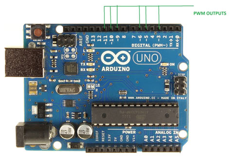
As shown in figure, an Arduino UNO has 6PWM channels, so we can get PWM (variable voltage) at any of these six pins. In this chapter we are going to use PIN3 as PWM output.
Required Components
Hardware: ARDUINO UNO, power supply (5v), 100uF capacitor ,LED, buttons (two pieces), 10KΩ resistor (two pieces).
Software: arduino IDE
Circuit Diagram and Explanation

The circuit is connected on breadboard as per the circuit diagram. However one must pay attention during connecting the LED terminals. Although the buttons show bouncing effect in this case it does not cause considerable errors so we need not worry this time.
The PWM from UNO is quite easy. While setting up a ATMEGA controller for PWM signal is not easy, we have to define many registers and settings for a accurate signal, however in ARDUINO we don’t have to deal with all those things.
By default all the header files and registers are predefined by ARDUINO IDE, we simply need to call them and that’s it we will have a PWM output at appropriate pin.
Now for getting a PWM output at a appropriate pin, we need to work on two things,
|
First we need to choose the PWM output pin from six pins, after that we need to set that pin as output.
Next we need to enable the PWM feature of UNO by calling the function “analogWrite(pin, value)” . Here ‘pin’ represent the pin number where we need PWM output we are putting it as ‘3’. So at PIN3 we are getting PWM output. Value is the turn ON duty cycle, between 0 (always off) and 255 (always on). We are going to increment and decrement this number by button press.
Using PWM pins in Arduino Uno is explained in the C code given below.
Complete Project Code
volatile int i=0;//initializing a integer for incrementing and decrementing duty ratio.
void setup()
{
                pinMode(3, OUTPUT);   // sets the pin3 as output
                pinMode(0, INPUT);// sets the pin0 as output
                pinMode(1, INPUT);// sets the pin1 as output
}

void loop()
{
                analogWrite(3, i);  // analogWrite values from 0 to 255
                if (digitalRead(0)==LOW)
                {
                                if (i<255)
                                {
                                                i++;//if pin0 is pressed and the duty ratio value is less than 255
                                                delay(30);
                                }
                }
                if (digitalRead(1)==LOW)
                {
                                if (i>0)
                                {
                                                i--;// if pin1 is pressed and the duty ratio value is greater than 0
                                                delay(30);
                                }
                }
}
Comments
If i want attach the frequency counter program with this program so what should i do?
Here is Frequency Counter using Arduino
hello, great project, i have done this and it is working, how can we add ac 200Watt motor for speed control with this same circuit by 2 switch , 1 for speed up and other for speed down. same as this circuit?
if i want to make that project but control by web page..so what should i do ?
Can I control ac fan using this program
Can we do led dimming without using those button, as i want to do this dimming automatically by sensing obstacle
A 100uF capacitor is present in the list of required components. However, I do not see it in the schematic.
???

De code pinMode 0 and 1 are nor working.
I modyfi pinMode(4, INPUT), and pinMode(7, INPUT)
and it's working
pin 0=rx and pin =tx.
Kind regards;
Henk Don
the Nederlands