")
Stepper motor is brushless DC motor, which can be rotated in small angles, these angles are called steps. Generally stepper motor use 200 steps to complete 360 degree rotation, means its rotate 1.8 degree per step. Stepper motor is used in many devices which needs precise rotational movement like robots, antennas, hard drives etc. We can rotate stepper motor to any particular angle by giving it proper instructions. Mainly two types of stepper motors are available, Unipolar and Bipolar. Unipolar is easier to operate, control and also easier to get. Here in this tutorial we are interfacing Stepper Motor with STM32F103C8 (Blue pill) board.
Materials Required
- STM32F103C8 (Blue pill)
- Stepper Motor(28BYJ-48)
- ULN2003 IC
- Potentiometer 10k
- Breadboard
- Jumper wires
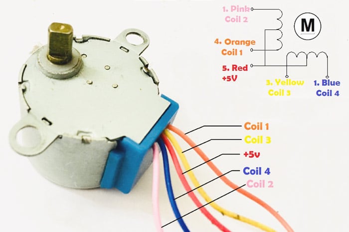
Stepper Motor (28BYJ-48)
28BYJ-48 is a Unipolar Stepper motor which requires 5V supply. The motor has a 4 coil unipolar arrangement and each coil is rated for +5V hence it is relatively easy to control with any microcontrollers like Arduino ,Raspberry Pi also STM32.But we need a Motor Drive IC like ULN2003 to drive it, because stepper motors consume high current and it may damage microcontrollers.
Another important data to notice is the Stride Angle: 5.625°/64. This means that the motor when operates in 8-step sequence will move 5.625 degree for each step and it will take 64 steps (5.625*64=360) to complete one full rotation. Other specifications are provided in datasheet below:

Also check interfacing with Stepper Motor with other Microcontrollers:
- Interfacing Stepper Motor with Arduino Uno
- Stepper Motor Control with Raspberry Pi
- Stepper Motor Interfacing with 8051 Microcontroller
- Interfacing Stepper Motor with PIC Microcontroller
Stepper motor can also be controlled without any Microcontroller, see this Stepper Motor Driver Circuit.
ULN2003 Motor Driver IC
It is used to drive the motor according to pulses received from microcontroller. Below is the picture diagram of ULN2003:

Pins (IN1 to IN7) are input pins and (OUT 1 to OUT 7) are corresponding output pins. COM is given Positive source voltage required for output devices. Further connections for stepper motor are given below in circuit diagram section.
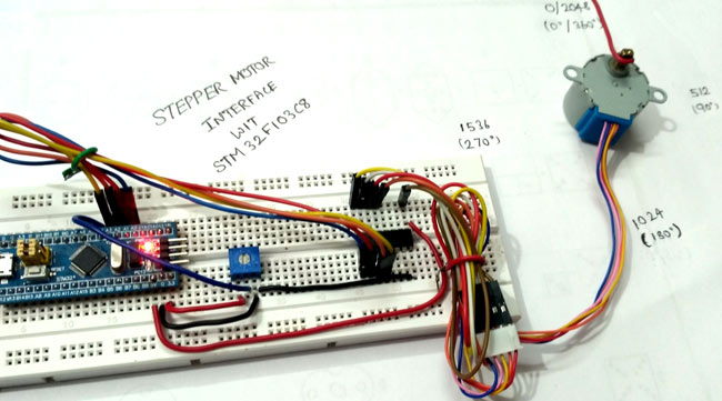
Circuit Diagram and Connections

Below is the connections explanation for above circuit diagram.
STM32F103C8 (Blue Pill)
As we can see in the below diagram, the PWM pins are indicated in wave format (~), there are 15 such pins which can be used for pulse output to stepper motor. We need only four pin, we use (PA0 toPA3).

STM32F103C8 with ULN2003 Motor Driver IC
Pins (PA0 to PA3) are considered as output pins that are connected with input pins (IN1-IN4) of the ULN2003 IC.
|
PINS OF STM32F103C8 |
PINS OF ULN2003 IC |
|
PA0 |
IN1 |
|
PA1 |
IN2 |
|
PA2 |
IN3 |
|
PA3 |
IN4 |
|
5V |
COM |
|
GND |
GND |
ULN2003 IC with Stepper Motor (28BYJ-48)
The output pins (OUT1-OUT4) of ULN2003 IC are connected to the stepper motors pins (Orange, Yellow, Pink, and Blue).
|
PINS OF ULN2003 IC |
PINS OF STEPPER MOTOR |
|
OUT1 |
ORANGE |
|
OUT2 |
YELLOW |
|
OUT3 |
PINK |
|
OUT4 |
BLUE |
|
COM |
RED |
STM32F103C8 with Potentiometer
A potentiometer is used as to set speed of the stepper motor.
|
POTENTIOMETER |
STM32F103C8 |
|
LEFT (INPUT) |
3.3 |
|
CENTRE(OUTPUT) |
PA4 |
|
RIGHT(GND) |
GND |
Rotating Stepper Motor with STM32F103C8
Below is few steps to operate the Stepper Motor:
- Set the speed of stepper motor by varying potentiometer.
- Then manually enter steps for rotation either in clockwise (+values) or anticlockwise direction(-values) via SERIAL MONITER present in ARDUINO IDE (Tools->Serial monitor) or CTRL+SHIFT+M.
- According to the input value given in serial monitor certain steps of rotation takes place in stepper motor.
For Example
|
VALUE GIVEN IN SERIAL MONITER |
ROTATION |
|
2048 |
(360) CLK WISE |
|
1024 |
(180)CLK WISE |
|
512 |
(90)CLK WISE |
|
-2048 |
(-360) ANTI CLK WISE |
|
-1024 |
(-180)ANTI CLK WISE |
|
-512 |
(-90)ANTI CLK WISE |
PROGRAMMING STM32 for Stepper Motor
Like the previous tutorial, we programmed the STM32F103C8 with Arduino IDE through USB port without using FTDI programmer. To learn about programming STM32 with Arduino IDE follow the link. We can proceed programming it like an Arduino. Complete code is given at the end of the project.
First we have to include the stepper library files #include <Stepper.h> for using stepper functions.
#include <Stepper.h>
Then we define no. of steps to complete on rotation, here we use 32 because we are using Full-Step (4 Step-sequence) so (360/32 = 11.25 degree). So for one step, the shaft moves 11.25 degree that is stride angle. In 4 Step sequence, 4 steps are required for one complete rotation.
#define STEPS 32
We can also use Half step mode where there is 8 step sequence (360/64=5.625) stride angle.
Steps per revolution = 360 / STEP ANGLE
As we are setting speed we must take analog value from PA4 that is connected to potentiometer. So we must declare pin for that
const int speedm = PA4
Then we have converted the analog value into digital by storing those values in variable of integer type, after that we have to map the ADC values for setting speed so we use the below statement. Learn more about using ADC with STM32 here.
int adc = analogRead(speedm);

int result = map(adc, 0, 4096, 1, 1023);
To set speed, we use stepper.setSpeed(result); We have speed range of (1-1023).
We must create instance like below to set the pins that are connected to motor. Be careful in these steps as most of them do a mistake here in this pattern. They give wrong pattern and because of that coils cant be energised.
Stepper stepper(STEPS, PA0, PA2, PA1, PA3);
Below statement is used to get the value of steps from serial monitor. For example we need 2048 values for one full rotation (32*64 = 2048) that is 64 will be the gear ratio and 32 will be half step sequence for one rotation.
rotate = Serial.parseInt();
Below code is used to call the instance and run the motor .If rotate value is 1 it calls the function stepper one time and one move is done.
stepper.step(rotate);
Complete code with Demonstration Video is given below. Also check all the stepper motor related projects here, with interfacing with various other microcontrollers
Complete Project Code
//STM32 stepper motor control code

//CIRCUIT DIGEST
#include <Stepper.h>                         // Include the Stepper motor header file

#define STEPS 32                             // change this to the number of steps on your motor

const int speedm = PA4;                      // Pin for input speed

Stepper stepper(STEPS, PA0, PA2, PA1, PA3);  // create an instance of the stepper class using the steps and pins

int rotate = 0;                                 //declare variable rotate with 0 for input rotation.

void setup()                                 //Setup() runs only once

{

  Serial.begin(9600);                        //begins serial communication at 9600baud rate

  pinMode(speedm,INPUT);                     //set pin PA4 as input

}
void loop()                                   //loop() runs infinitely

{

  if (Serial.available()>0)                   //Checks if serial data is entered or not in serial monitor

  {

    rotate = Serial.parseInt();                  //gets the value for rotation from serial monitor

    int adc = analogRead(speedm);             //read analog value from pin PA0

    int result = map(adc, 0, 4096, 0, 1023);  //maps the result of ADC from (0to4096)with (0to1023)

    stepper.setSpeed(result);                 //sets the speed of motor

    stepper.step(rotate);                        //makes the motor to rotate

    Serial.println(rotate);                      //prints the value you specified to rotate

  }

}
