
A stepper motor is a type of DC motor that works in discrete steps and is used everywhere from a surveillance camera to sophisticated robots and machines. NEMA 17 stepper motor provide accurate control and can be differentiated based on torque, steps per revolution, and input voltage. In our previous project, we controlled a 28-BYJ48 stepper motor using Arduino. 28-BYJ48 has relatively lower torque than the other stepper motors, like NEMA 14, NEMA 17.
In this tutorial, we are going to control a NEMA17 stepper motor with Arduino Uno and an A4988 stepper driver module. The Nema17 stepper motor has higher torque and operating voltage than the 28-BYJ48. Here, a potentiometer will also be attached to control the direction of the stepper motor.
Table of Contents
- Components Required
- Understanding the NEMA 17 Stepper Motor
- NEMA 17 Technical Specifications
- A4988 Stepper Driver Module - Complete Guide
- Key Features from A4988
- └ Specifications of A4988
- Circuit Diagram
- Arduino Code for NEMA 17 Stepper Motor Control
- Comparison: A4988 vs. Other Popular Drivers
- GitHub Repository
- Troubleshooting
Components Required for NEMA 17 Arduino Stepper Motor Control
- Arduino UNO
- NEMA17 Stepper Motor
- A4988 Stepper Driver Module
- 47 µf Capacitor
- Potentiometer
Understanding the NEMA 17 Stepper Motor

The operation of the NEMA 17 stepper motor is similar to normal Stepper Motors. A NEMA 17 stepper motor has a 1.7 x 1.7-inch faceplate, and it usually has more torque than the smaller variants, such as NEMA 14. This motor has six lead wires, and the rated voltage is 12 volts. It can be operated at a lower voltage, but the torque will drop. Stepper A do not rotate in steps, and the NEMA17 motor has a step angle of 1.8 deg. means it covers 1.8 degrees in every step. The wiring diagram for NEMA17 is given below.

The NEMA 17 typically uses a unipolar six-wire arrangement with two independent windings. Understanding the NEMA 17 stepper motor pinout is crucial for proper connection:
| Wire Color | Function | Winding |
| Black | Center tap | Winding A |
| Yellow | Coil end | Winding A |
| Green | Coil end | Winding A |
| White | Center tap | Winding B |
| Red | Coil end | Winding B |
| Blue | Coil end | Winding B |
As you can see that this motor has a Unipolar six-wire arrangement. These wires are connected in two split windings. Black, Yellow, and Green wires are part of the first winding, where Black is center tap, and Yellow and Green are coil ends, while Red, White, and Blue is part of a second winding, in which White is center tap, and Red and Blue are coil ends. Normally, center tap wires are left disconnected.
Calculating Steps Per Revolution
Steps Per Revolution for a particular stepper motor is calculated using the step angle of that stepper motor. So in this case, the NEMA 17 step angle is 1.8 degrees.
Steps per Revolution = 360/ step angle
360/1.8 = 200 Steps Per Revolution
NEMA 17 Technical Specifications
- Rated Voltage: 12V DC
- Step Angle: 1.8 deg.
- No. of Phases: 4
- Motor Length: 1.54 inches
- 4-wire, 8-inch lead
- 200 steps per revolution, 1.8 degrees
- Operating Temperature: -10 to 40 °C
- Unipolar Holding Torque: 22.2 oz-in
Also, check various stepper motor-related projects here, which not only include basic interfacing with various microcontrollers but also have robotics projects which involve stepper motors.
A4988 Stepper Driver Module - Complete Guide
A stepper driver module controls the operation of a stepper motor. Stepper drivers send the current to the stepper motor through various phases.
The A4988 Nema 17 stepper driver is a microstepping driver module that is used to control bipolar stepper motors. This driver module has a built-in translator, which means that we can control the stepper motor using very few pins from our controller.

Key Features from A4988
» Microstepping: Five resolution modes, ranging from full step to 1/16 step.
» Overcurrent Protection: Provided by thermal shutdown and current regulation.
» Ease of Interface: Simple step and direction control.
» Wide Voltage Range: 8V to 35V input voltage.
» Current control: Current level is adjustable via onboard potentiometer.
Using this Nema 17 motor driver module, we can control the stepper motor by using only two pins, i.e., STEP and DIRECTION. The STEP pin is used to control the steps, while the DIRECTION pin is used to control the direction of the motor. A4988 driver module provides five different step resolutions: full-step, half-step, quarter-step, eight-step, and sixteenth-step. You can select the different step resolutions using the resolution selector pins (MS1, MS2, and MS3). The truth table for these pins is given below:
| MS1 | MS2 | MS3 | Microstep Resolution |
| Low | Low | Low | Full Step |
| High | Low | Low | ½ Step (Half Step) |
| Low | High | Low | ¼ Step (Quarter Step) |
| High | High | Low | 1/8 Step (Eighth Step) |
| High | High | High | 1/16 Step (Sixteenth Step) |
Specifications of A4988
Max. Operating Voltage: 35V
Min. Operating Voltage: 8V
Max. Current Per Phase: 2A
Microstep resolution: Full step, ½ step, ¼ step, 1/8 and 1/16 step
Reverse voltage protection: No
Dimensions: 15.5 × 20.5 mm (0.6″ × 0.8″)
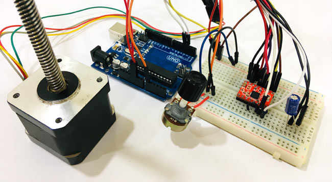
Circuit Diagram: NEMA 17 with Arduino and A4988

This section provides complete NEMA 17 stepper motor wiring details for Arduino control.
A circuit diagram to control a NEMA 17 stepper motor with Arduino is given in the above image. As A4988 module has a built-in translator, which means we only need to connect the Step and Direction pins to the Arduino. The step pin is used for controlling the steps, while the direction pin is used to control the direction. The stepper motor is powered using a 12V power source, and the A4988 module is, via Arduino. A potentiometer is used to control the direction of the motor.
If you turn the potentiometer clockwise, then the stepper will rotate clockwise, and if you turn the potentiometer anticlockwise, then it will rotate anticlockwise. A 47 µf capacitor is used to protect the board from voltage spikes. MS1, MS2, and MS3 pins are left disconnected, which means the driver will operate in full-step mode.
Complete connections for Arduino Nema 17 A4988 are given in the table below.
S.NO. | A4988 Pin | Connection |
1 | VMOT | +ve Of Battery |
2 | GND | -ve of Battery |
3 | VDD | 5V of Arduino |
4 | GND | GND of Arduino |
5 | STP | Pin 3 of Arduino |
6 | DIR | Pin 2 of Arduino |
7 | 1A, 1B, 2A, 2B | Stepper Motor |
Arduino Code for NEMA 17 Stepper Motor Control
Complete code with working video control Nema 17 with Arduino is given at the end of this tutorial; here we are explaining the complete program to understand the working of the project.
First of all, add the stepper motor library to your Arduino IDE. You can download the stepper motor library from here.
After that, define the no of steps for the NEMA 17. As we calculated, the no. of steps per revolution for NEMA 17 is 200.
#include <Stepper.h>
#define STEPS 200
After that, specify the pins to which the driver module is connected and define the motor interface type as Type1 because the motor is connected through the driver module.
Stepper stepper(STEPS, 2, 3);
#define motorInterfaceType 1
Next, set the speed for the stepper motor using stepper.setSpeed function. The maximum motor speed for NEMA 17 is 4688 RPM, but if we run it faster than 1000 RPM torque falls off quickly.
void setup() {
    stepper.setSpeed(1000);
Now in the main loop, we will read the potentiometer value from the A0 pin. In this loop, there are two functions: one is potVal, and the other is Pval. If the current value, i.e., potVal, is higher than the previous value, i.e., Pval, then it will move ten steps in the clockwise direction, and if the current value is less than the previous value, then it will move ten steps in the counterclockwise direction.
potVal = map(analogRead(A0),0,1024,0,500);,if (potVal>Pval)
      stepper.step(10);
  if (potVal<Pval)
      stepper.step(-10);
Pval = potVal;
Now connect the Arduino with your laptop and upload the code into your Arduino UNO board using Arduino IDE, select the Board and port no and then click on the upload button.
Now you can control the direction of the Nema17 stepper motor using the potentiometer. The complete working of the project is shown in the video below. If you have any doubts regarding this project, post them in the comment section below.
Comparison: A4988 vs. Other Popular Drivers
| Driver | Max Current | Microstepping | Noise Level | Best For |
| A4988 | 2A | Up to 1/16 | Moderate | Budget projects, learning |
| DRV8825 | 2.2A | Up to 1/32 | Moderate | Higher resolution needs |
| TMC2208 | 2A | Up to 1/256 | Very quiet | Noise-sensitive applications |
| TMC2209 | 2A | Up to 1/256 | Very quiet | Advanced features, UART control |
| TB6600 | 4A | Up to 1/16 | Low | High-current motors, industrial |
Technical Summary and GitHub Repository
A technical summary explains the project’s concept and functionality in a simplified form, whereas the GitHub repository showcases the full technical execution and source code. This combination ensures transparency and reproducibility.


Troubleshooting Common Issues and Solutions
Problem | Possible Cause | Solution |
Motor doesn't move | Current limit too low or wiring error | Check connections, adjust A4988 potentiometer |
Motor vibrates/hums | Incorrect wiring or phase sequence | Swap one coil pair (1A with 1B) |
Motor gets hot | Current limit set too high | Reduce A4988 Vref, add heatsink |
Driver IC hot | Insufficient cooling | Add heatsink, reduce current, improve airflow |
Erratic movement | Power supply issues | Check capacitor placement, use adequate PSU |
No response to pot | Analog pin issue | Verify A0 connection, check potentiometer |
Frequently Asked Questions on Nema 17 Stepper Motor
⇥ 1. What distinguishes a NEMA 14 stepper motor from a NEMA 17 stepper motor?
With a faceplate measuring 1.7×1.7 inches, the NEMA 17 holds a slightly wider area. Also, the NEMA 17 provides significantly higher torque than the NEMA 14. It is common to see the NEMA 14 produce about 20-30 Ncm torque, while the NEMA 17 can actually produce 40-60 Ncm torque. Since the NEMA 17 is stronger, this force can hold better during application, while the motor may weigh a bit more and draw more power.
⇥ 2. Will I need a driver to use a NEMA 17 stepper motor?
You cannot drive a NEMA motor directly from the Arduino. Stepper motors need phase sequencing in the coil to power them, as well as require a higher current (1-2A) than the Arduino pins can provide (max 40mA). You will need a driver, such as an A4988 or DRV8825 or TMC2208, to manage the power delivery and phase control for safety.
⇥ 3. How do I make my NEMA 17 stepper motor go faster?
You can increase the RPM value in stepper.setSpeed() to make your motor go faster, or distribute or pulse the green step pin at a faster rate. The torque of the motor decreases at fast RPMs, but the upper limit is determined during the construction of the circuitry. If you want to achieve more than 600 RPM, then you will need to first make sure you have a higher voltage, like 24V instead of 12V, while using microstepping and keep the mechanical load light to allow for smoother RPM and upper performance.
⇥ 4. Why does my NEMA 17 stepper motor get hot when in use?
Stepper motors tend to run hot. (50-80°C is a "normal" range). They hold constant current while not moving, leading to the potential for heat to build. Too much heat means the current limit is set too high in the driver. Adjust the A4988's potentiometer, attach a heatsink, or only activate the motor when it is moving.
⇥ 5. What is the maximum speed at which I can run a NEMA 17 stepper motor?
The NEMA 17 will run 1000-1500 RPM with 24V power and appropriate tuning, but the torque drops off heavily beyond 600 RPM. The max usable speed can vary due to load and voltage, as well as the capacity of the driver being used. For constant torque loading, typically work between 200-600 RPM. Once you exceed the upper range, you will begin needing lighter loads, and you may start using microstepping to keep the motor stable.
⇥ 6. How many NEMA 17 motors can I control with one Arduino?
Depending on your Arduino, it can control multiple NEMA 17 motors. The number of motors you can control is determined by how many digital pins you have available. Each motor requires 2 pins (DIR and STEP). For example, the Arduino UNO has 14 digital pins available, meaning you can control 7 motors. In each case, you will want to use an external driver for each motor, and note that you will need a power supply that can provide current to all motors at once.
⇥ 7. What power supply does a NEMA 17 stepper motor need?
12V DC supplies rated for 2A per motor represent the minimum, while 3-4A are better for headroom. For enhanced performance at higher speeds, a 24V supply is ideal, featuring current-limiting drivers. Make sure that the supply gives out clean DC power; if not, put bulk capacitors (100-470µF) near the driver to suppress voltage spikes and EM interference.
Conclusion
This detailed guide explained all that you need to know in order to control a NEMA 17 stepper motor with Arduino programming language, and a NEMA 17 stepper motor with an A4988 driver module. You learned what NEMA 17 means, how to wire the NEMA 17 stepper motor properly, how to connect the pins, how to program the Arduino, and how to troubleshoot issues. The NEMA 17 stepper motor Arduino code supplied here is a good start to building your own motion control projects. Gain experience with Arduino stepper motor programming and NEMA 17 stepper motor controller ways.
Projects using Stepper Motor
Previously, we have used a Stepper Motor to build many interesting projects. If you want to know more about those topics, links are given below.

Stepper Motor Control with A4988 Stepper Motor Driver and Arduino UNO
In this A4988 stepper motor driver tutorial, we'll be looking at how to interface and connect the A4988 stepper motor driver module Arduino and go over the basic principles of stepper motors, A4988 stepper motor driver pinout, wiring connections, and programming examples. Whatever you are building, whether it be a 3D printer, CNC machine, or robotics project, you will learn how to implement the A4988 stepper driver Arduino.

Stepper Motor Interfacing with 8051 Microcontroller
The Stepper motor with 8051 microcontroller working principle is to send digital pulses to each of the motor windings in the correct sequence. The motor will move one step per pulse, providing good control of position without the need for feedback sensors.
A stepper motor driver circuit is essentially a decade binary counter circuit designed to control stepper motors with precision. The name of this motor is given because the rotation of the shaft is in step form, which is different from DC or any other motor.
Complete Project Code
#include <Stepper.h>
#define STEPS 200
// Define stepper motor connections and motor interface type. Motor interface type must be set to 1 when using a driver
Stepper stepper(STEPS, 2, 3); // Pin 2 connected to DIRECTION & Pin 3 connected to STEP Pin of Driver
#define motorInterfaceType 1
int Pval = 0;
int potVal = 0;
void setup() {
  // Set the maximum speed in steps per second:
  stepper.setSpeed(1000);
}
void loop() {

  potVal = map(analogRead(A0),0,1024,0,500);
  if (potVal>Pval)
      stepper.step(10);
  if (potVal<Pval)
      stepper.step(-10);
Pval = potVal;

}

Controlling NEMA 17 Stepper Motor with Arduino and A4988 Stepper Driver Module
Hi
What changes to the code if any need to be made to make the stepper motor turn at 1/4 step and as slowly as possible. I am planning to use this circuit to control a HF magnetic loop antenna's variable capacitor so it needs to be slow , small steps for accuracy and it must stop where AND when I want it to stop.
cheers Mike