

Most advanced electronics PCB assembly lines have pick and place machines to pick components from an SMD reel and place it on a PCB. But this is not possible when you are doing medium-scale production or using THT (through-hole type) components on your PCB. This scenario holds true, in most low-cost board assemblies like LED drivers, transformerless power supplies, etc. In order to help speed up this assembly process and prepare the required number of components we have built this Arduino Based Resistor Cutting Machine.
This machine can handle any tapped component reels like resistors reels, diodes reels, or anything of that kind. It can draw a particular number of components from a reel and cut it into the required quantity. This way we can easily cut an entire reel into small pieces of the required quantity.
Basic Mechanism and Functionality
When I started with this project, there was one project on the internet called resistor cutting Robot by Pablo. The project was very impressive but I wanted to modify it to make it more reliable and easier for everyone to build so I added the following pointers:
- The machine should be easy to build, meaning anyone with a 3D printer should be able to build it, without the need of having access to many other power tools.
- Improve the accuracy and reliability of the machine by adding a MOC7811 opt isolator sensor which will act as feedback to our Arduino. This will help to know how much components are being pushed every single time
- Replace the wooden base with Aluminum extrusion which is easily available in the market and also make the design more robust and easier to work.
- Change the cutting mechanism from using stepper motors to Servo motors to make the design simpler and easier to build.
- Make the complete design available for everyone as open-source by providing the editable CAD files, schematics, and Arduino code.
Materials Required to Build a Resistor Reel Cutting Machine
As explained earlier the idea of this build was to keep the materials and tools required as simple and as easy as possible. You will only need the following components to build your resistor cutting machine.
Mechanical Components
- Aluminum Extrusion Profile 20x40 6T Slot
- Smooth Shaft Rod 8mm Diameter
- Threaded Rod 8mm Diameter
- Nema17 motor Coupling for 8mm soft shaft
- Flanged Ball Bearing 8mm bore – 2pcs
- Pillow Block Mount 8mm bore – 2pcs
- Cast Corner Bracket for 2020 Aluminum Extrusion – 4pcs
- Sliding T nut for 2020 Aluminum Extrusion – 20 pcs
- M4 6mm Socket Screws for T nut – 20 pcs
- Timing Belt for pully
Electronic Components
- Nema17 Stepper Motor
- MG90S Servo Motor with Metal Gear
- Arduino Nano
- 16x2 LCD Screen
- A4988 Stepper Motor Driver module
- MOC7811 opto-coupler sensor
- 12V 2A DC adapter
- Push buttons
- 50V 100uf electrolytic capacitor
- Connecting Wires and perf board
Mechanical Construction of Arduino Resistor Cutting Machine
The complete Mechanical Construction for the machine is split into small segments and is explained below.
Driving Mechanism:
We have used the NEMA17 stepper motor as the main drive motor for our machine. If you are new to using NEMA17 stepper motors, you can check out this article on how to use NEMA17 with A4988 stepper motor driver module which explains the basics. The NEMA17 motor is connected to a 8mm soft shaft using a coupler as shown below, this way when the motor rotates the soft shaft also rotates with it.
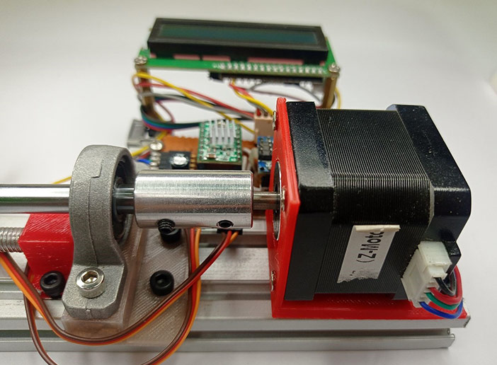
The reason for using a stepper motor is that we can control the number of steps uniformly throughout the operation of the machine and we can have a uniform feed. As you can see in the above image, we have 3D printed a motor mount to keep the NEMA17 motor fixed to the aluminum extrusion bar.
Feeding Mechanism:
The next stage of the machine is the feeding mechanism, which is achieved using a soft shaft, a threaded rod, a couple of pillow blocks, and feeding rollers as shown below.
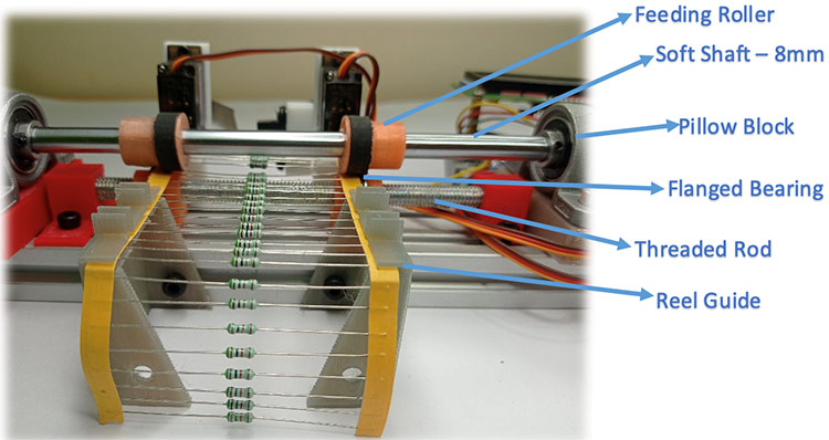
Feeding Roller: The feeding roller is a 3d printed part that has a timing belt glued to it. The rubber in the timing belt provides enough friction and pressure to push the reel strip uniformly.
Soft Shaft: The soft shaft is coupled to the stepper motor and the feeding roller is screwed tight on the soft shaft. This way the feeding rollers can be set apart at the required distance and the roller rotates along with the stepper motor.
Pillow Block: We have used two pillow blocks on either side of the soft shaft to make sure that the soft shaft is in parallel to the aluminum extrusion. Also, these two blocks help us in setting the distance between the soft shaft and threaded rod and thus controlling the pressure extorted by the rollers on the resistor reel.
Threaded Rod and Flanged Bearing: A 8mm Threaded rod with a Flanged bearing mounted under the soft shaft. The flanged bearings help in holding the resistor reel in place and also rotates freely as the roller moves, thus feeding the reel into the cutting section. The flanged bearing is not completely visible in the above image but you can check out the video linked in the bottom of this page for better understanding.
Reel Guide: The reel guide is again a couple of 3D printed parts which is mounted to the aluminum extrusion. As you can see in the image, the resistor reel is fed into the rollers through this reel guide to make sure that the reel always enters perpendicular to the feeding rollers.
Counting and Feedback Mechanism:
Despite having the feeding mechanism well planned (as much as I could), every now and then the resistor reels do tend to slip and hence the feeding does not stay uniform. Hence had to introduce a sensor to count how many resistors are being fed into the machine before it gets cut. Also, this way we get feedback from the machine and we can ensure that everything is running smooth.
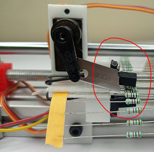
The above image shows how we have mounted a MOC7811 optocoupler sensor to count the resistors or diodes being pushed out of the feeding mechanism. Do note that the distance between the sensor’s transmitter and the receiver has been cut and modified to allow the complete strip to pass through the resistor.
Chopping Mechanism:
The last Mechanism of the machine is the Chopping Mechanism, to make this work we have used two servo motors with blades attached to its horns as shown below.
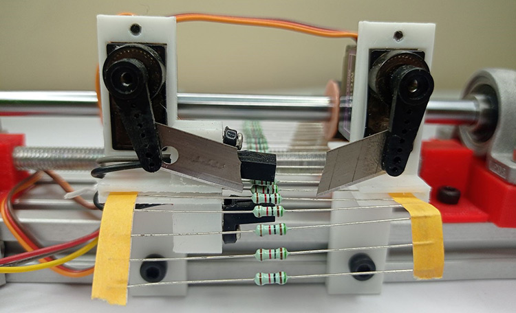
I still believe that this area could use a lot of improvements, mainly with the way the blades have been mounted. Maybe someone reading this can suggest better alternatives. Although using two servos do provide an advantage since the blades can be controlled independently, we can adjust the servo angel individually to keep the blades close to the strip and make sure they travel at the same speed and same time to ensure a uniform cut on either side.
3D Printing all the Required Parts
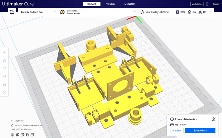
This Arduino based resistor cutting machine has 13 parts that have to be 3D printed. I have uploaded all the STL files on thingverse which you can download and print on your own using the link below.
Download STL files for Resistor Cutting Machine
Apart from the STL files, you will also find editable files which you can use on fusion 360 to modify or improvise the designs.
I have used cura to slice all the 13 STL files and printed them using my Ender 3D printer, since there were no high accuracy parts I have set cura to slice with low quality (0.28mm layer thickness) and added support only to parts hanging above build plate. The entire print should take you around 7.5 hours as shown in the screenshot above. You can also find the Gcode for the same in the thing verse link shared above.
Circuit Diagram for Arduino Based Resistor Reel Cutting Machine
The complete circuit diagram for our DIY Arduino Resistor cutting machine is shown below-

As you can see the circuit is very simple, we have used a 12V 2A adapter to power the entire setup. The onboard 5V regulator on nano is used to power the MOC7811 sensor and servo motor using the 5V pin on the Arduino board. The 16x2 LCD is connected to Arduino nano using an I2C module on the I2C pins of Arduino namely pin A4 and A5.
The left and right servo motor is connected to PWM pins 9 and 10 respectively. The A4988 Stepper Driver Module’s Enable, Step, and Dir pins are connected to D6, D3, and D4 respectively. We have used the Enable pin to cut power to the stepper motor whenever we are not using it. The MOC7811 is connected to pin A0 and push-button is connected to pin D8. The push-button is used to start or stop the machine during operation.
On the above schematics, since fritzing does not have a MOC7811 component we have shown its circuit separately. The 220-ohm resistor is used to limit the current flowing to the photodiode and the 10K resistor is used to pull up the output pin of the sensor when an object is detected the Sigout pin reads 0V else it will read 5V. This pin is connected to the Arduino analog pin to check if any component is crossing the sensor.
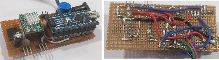
As you can see in the above image I have built the complete circuit over a zero PCB and have provided header pins to connect the stepper motor, servo motors, LCD display, and sensor. Then I have used the L-clamps and a few screws to mount the board and the LCD display in place as you can see in the below image-
Programming Resistor Reel Cutting Machine using Arduino
The complete code for resistor cutting machine can be found at the bottom of the page, in this section I will explain the important segments of the code. The complete code was written and tested for Arduino nano using old bootloader, if you have any questions you can leave them in the comment section below.
Inside the void setup function, we start by defining the type of input and output pins. Note that we have defined the push button pin as input pull-up, hence whenever this button is pressed the digital read will give us a zero.
    // Sets pinmodes
  pinMode(stepPin,OUTPUT);
  pinMode(dirPin,OUTPUT);
  pinMode(enablePin,OUTPUT);
  pinMode(pushButton,INPUT_PULLUP);
Then we set our servo motors in their initial position, this will move the blades out of the feeding path and will let us load the resistor reel in place. You might wanna tweak the values of left_pos and right_pos based on your requirement.
  //Move servo to default position
  left_servo.attach(9);  // attaches the servo on pin 9 to the servo object
  left_servo.write(left_pos);
  delay (1000);
  right_servo.attach(10); //attaches the servo on pin 10 to the servo object
  right_servo.write(right_pos);
  delay(1000);
Once everything is initialized, we have used while loop to hold the program while reading the status of the push button. Only when the push button is pressed the code will move further. This way the user will have time to prepare the machine before it starts its job.
  while(digitalRead (pushButton) ==HIGH) //Wait here till this the button is long pressed
  {
    }
We have used a function called step_forward() which will move the stepper motor forward by one single step. While doing that it will also increase a variable called step_count and will check if there are any faults while feeding the resistor reel. Meaning when the motor is rotating the resistor reel should move forward and the MOC7811 sensor should be triggered by the resistor moving in between it, if the sensor is not seeing any components despite the stepper motor moving forward it means there is a fault and we have to stop. The fault condition is candled by the else loop in the below code.
void step_forward()
{
  if (Step_count < Max_steps_before_fault)
  {
    digitalWrite(dirPin,HIGH); // Enables the motor to move in a particular direction
    digitalWrite(stepPin,LOW);
    delayMicroseconds(1000);
    digitalWrite(stepPin,HIGH);
    delayMicroseconds(1000);
    Step_count++;
  }
  else
  {
  lcd.clear();
  lcd.setCursor(3,0);
  lcd.print("Step Fault");
  digitalWrite(enablePin,HIGH);    //Diable Stepper Motor
  while (1);
    }
}
Moving on, we have another function called chop(). This function is used to activate the servo motors and cut the resistor reel after extruding the required number of components. The important thing here is to move both the servo motors at the same time and to the same distance we have used two for loops as shown below to achieve the same.
void chop()
{
  for (int steps = 0; steps <= 120; steps += 1) {
    left_pos = 170-steps; //moves servo from 160 to 60
    right_pos = 60+steps; //moves servo from 60 to 160
    left_servo.write(left_pos);
    right_servo.write(right_pos);
    delay(3);
  }
  delay(100);
  for (int steps = 0; steps <= 120; steps += 1) {
    left_pos = 60+steps; //moves servo from 60 to 160
    right_pos = 170-steps; //moves servo from 160 to 60
    left_servo.write(left_pos);
    right_servo.write(right_pos);
    delay(3);
  }
}
Inside the void loop, there is nothing much we have to do. We just have to rotate the stepper motor till the sensor picks up a resistor. We have also used a delay of 20 milliseconds between every step of the motor to slow it down.
  //ROTATE the STEPPER TILL WE FIND A RESISTOR
  if (sensorValue<500)//if no resistor is found
    {
     step_forward();
     delay(20);
    }
If the sensor is interrupted by a resistor, we will register it by incrementing the variable Resistor_count and then proceed with stepping forward.
  //IF RESISTOR DETECTED - Step forward till the resistor is passed
  if (sensorValue>500)//resistor detected
    {
     Resistor_count = Resistor_count+1;
     Step_count=0;
     while (sensorValue>500)//while resistor is still under sensor
      {
        step_forward();
        sensorValue = analogRead(A0);
        delay(20);
      }
    }
If the machine has extruded the required number of resistors it's time to chop the resistor reel and the below piece of code does exactly the same. The variable chop count can be changed based on the required number of resistors you want your machine to cut.
   //IF COUNT REACHED
   if (Resistor_count==Chop_Count)
   {
    step_forward();step_forward();step_forward();step_forward(); step_forward();step_forward(); //few steps forward to cut exactly in the middle of two resitors
     chop();
     Total_cut++;
     Resistor_count=0;
     delay(200);
   }
Arduino Resistor Cutting Machine in Action
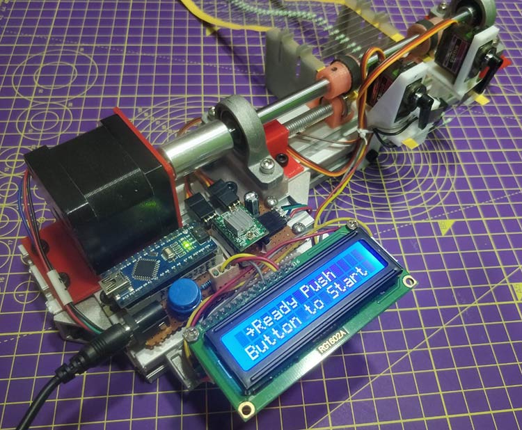
Using the machine is fairly simple. Just powered it on and the machine will initialize, after that, you will be prompted to press a button. But, before that take your resistor or any other taped components reel and feed it into the machine. At this stage, the stepper motor will be disabled, so you will be able to move the motor manually to set reel in right place as shown in the image below.

After this, just press the start button and our machine will kick into action. If you want to see the complete working you can check out the video linked at the bottom of the page.
So, with this, I am concluding this article. Hope you enjoyed reading it and learned something useful, if you have any suggestions or ideas to improve it please drop them in the comment section, I would love to hear them. Also, check out our forums if you want to ask any questions about this or any other similar projects.
Complete Project Code
/* Resistor cutting CNC Machine

 *  Servo is connected to PWM pins 9 and 10

 *  A4988 Stepper Driver Enable, Step and Dir pincs connected to D6, D3 and D4 resp.

 *  I2C LCD dipslay connected to A4 and A5

 *  MOC7811 is connected to A0

 *  Push Button Connected to D8

*/

#include <Servo.h>

#include <Wire.h>

#include <LiquidCrystal_I2C.h>

// defines pins numbers

const int stepPin = 3;

const int dirPin = 4;

const int enablePin = 6;

const int pushButton = 8;
const int  Max_steps_before_fault=25;

const int Job_Complete = 20;
int Chop_Count = 0;
int Resistor_count = -1;

int Step_count =0;

int Total_cut = 0;
int left_pos = 170;    // variable to store the servo position

int right_pos =60;
Servo left_servo;

Servo right_servo;
LiquidCrystal_I2C lcd(0x27, 16, 2);

void setup() {
    // Sets pinmodes

  pinMode(stepPin,OUTPUT);

  pinMode(dirPin,OUTPUT);

  pinMode(enablePin,OUTPUT);

  pinMode(pushButton,INPUT_PULLUP);
  //Diable Stepper Motor

  digitalWrite(enablePin,HIGH);

  Serial.begin(9600);// initialize serial communication at 9600 bits per second:

  lcd.begin ();

  lcd.backlight();
  //Move servo to default position

  left_servo.attach(9);  // attaches the servo on pin 9 to the servo object

  left_servo.write(left_pos);

  delay (1000);

  right_servo.attach(10); //attaches the servo on pin 10 to the servo object

  right_servo.write(right_pos);

  delay(1000);
  if (digitalRead (pushButton) ==HIGH)

  Chop_Count = 5;

  else

  Chop_Count =20;

  lcd.clear();

  lcd.setCursor(1,0);

  lcd.print("Resistor Cutter");

  lcd.setCursor(4,1);

  lcd.print("Mode Set");

  delay(3000);
  lcd.clear();

  lcd.setCursor(1,0);

  lcd.print(" ~Chop "); lcd.print(Chop_Count); lcd.print(" pcs");

  lcd.setCursor(0,1);

  lcd.print(" Press to Start");
  while(digitalRead (pushButton) ==HIGH) //Wait here till this the button is long pressed

  {

    }
//Enable Stepper Motor

  digitalWrite(enablePin,LOW);

  lcd.clear();

  lcd.setCursor(0,0);

  lcd.print("R_Count:  /5"); //display the count in 8th place

  lcd.setCursor(0,1);

  lcd.print("Job:  /20 ");//display number of pcs at 4 and Steps at 14

  delay (1000);

}

void step_forward()

{

  if (Step_count < Max_steps_before_fault)

  {

    digitalWrite(dirPin,HIGH); // Enables the motor to move in a particular direction

    digitalWrite(stepPin,LOW);

    delayMicroseconds(1000);

    digitalWrite(stepPin,HIGH);

    delayMicroseconds(1000);

    Step_count++;

  }

  else

  {

  lcd.clear();

  lcd.setCursor(3,0);

  lcd.print("Step Fault");

  digitalWrite(enablePin,HIGH);    //Diable Stepper Motor

  while (1);

    }

}

void chop()

{


  for (int steps = 0; steps <= 120; steps += 1) {

    left_pos = 170-steps; //moves servo from 160 to 60

    right_pos = 60+steps; //moves servo from 60 to 160

    left_servo.write(left_pos);

    right_servo.write(right_pos);

    delay(3);

  }

  delay(100);


  for (int steps = 0; steps <= 120; steps += 1) {

    left_pos = 60+steps; //moves servo from 60 to 160

    right_pos = 170-steps; //moves servo from 160 to 60

    left_servo.write(left_pos);

    right_servo.write(right_pos);

    delay(3);

  }

}
void loop() {
  lcd.setCursor(14,1);

  lcd.print(Step_count);//display  Steps at 14

  lcd.setCursor(8,0);

  lcd.print(Resistor_count+1); //display the count in 8th place

  lcd.setCursor(4,1);

  lcd.print(Total_cut);//display  pcs at 4
  int sensorValue = analogRead(A0); // read the input on analog pin 0 from MOC7811
  //ROTATE the STEPPER TILL WE FIND A RESISTOR

  if (sensorValue<500)//if no resistor is found

    {

     step_forward();

     delay(20);

    }
  //IF RESISTOR DETECTED - Step forward till the resistor is passed

  if (sensorValue>500)//resistor detected

    {

     Resistor_count = Resistor_count+1;

     Step_count=0;

     while (sensorValue>500)//while resistor is still under sensor

      {

        step_forward();

        sensorValue = analogRead(A0);

        delay(20);

      }

    }
   //IF COUNT REACHED

   if (Resistor_count==Chop_Count)

   {

    step_forward();step_forward();step_forward();step_forward(); step_forward();step_forward(); //few steps forward to cut exactly in the middle of two resitors

     chop();

     Total_cut++;

     Resistor_count=0;

     delay(200);

   }
   //Press the button for emergency stop

   if (digitalRead (pushButton) ==LOW)

   {

      lcd.clear();

      lcd.setCursor(0,0);

      lcd.print(" Emergency Stop");

      digitalWrite(enablePin,HIGH);    //Diable Stepper Motor

      while (1);

    }
   //Stop the machine after 20 cuts

      if (Total_cut == Job_Complete)

   {

      lcd.clear();

      lcd.setCursor(0,0);

      lcd.print(" Job Completed ");

      digitalWrite(enablePin,HIGH);    //Diable Stepper Motor

      while (1);

    }
Comments
hi, the software doesn't work
Very cool project! I would like to build it but what is the exact part number of the NEMA 17 motor? I can find a lot of them with different specs. Thank you

wow... I literally want to build this just because you gave me everything needed to do it, even though I have zero need for this mechanism. Love it. this is how its done. great job