

Power electronic switches like BJT, SCR, IGBT, MOSFET, and TRIAC are very important components when it comes to switching circuits like DC-DC converters, Motor Speed Controllers, Motor Drivers, and Frequency Controllers etc. Each device has its own unique property and thus they have their own specific applications. In this tutorial we will learn about the TRIAC, which is a bidirectional device meaning it can conduct in both the direction. Due to this property TRIAC is exclusively used where sinusoidal AC supply is involved.
Introduction to TRIAC
The term TRIAC stands for TRIode for Alternating Current. It is a three terminal switching device similar to SCR (Thyristor) but it can conduct in both the directional since it construct by combining two SCR in anti-parallel state. The symbol and pin out of TRIAC is shown below.
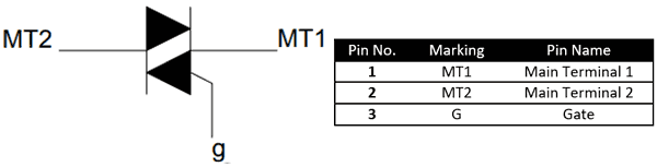
Since the TRIAC is a bi-directional device the current can either flow from MT1 to MT2 or from MT2 to MT1 when the gate terminal is triggered. For a TRIAC this trigger voltage that is to be applied to the gate terminal can either be positive or negative with respect to terminal MT2. Thus this puts the TRIAC into four operating modes as listed below
- Positive Voltage at MT2 and positive pulse to gate (Quadrant 1)
- Positive Voltage at MT2 and negative pulse to gate (Quadrant 2)
- Negative Voltage at MT2 and positive pulse to gate (Quadrant 3)
- Negative Voltage at MT2 and negative pulse to gate (Quadrant 4)
V-I Characteristics of a TRIAC
The below picture illustrates the status of TRIAC in each quadrant.
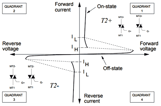
The turn on and turn off characterises of the TRIAC can be understood by looking at the VI characterises graph of the TRIAC which is also shown in the above picture. Since the TRIAC is just a combination of two SCR in anti-parallel direction the V-I characteristics graph looks similar to that of an SCR. As you can see the TRIAC mostly operates in the 1st Quadrant and the 3rd Quadrant.
Turn-On Characteristics
To turn on a TRIAC a positive or negative gate voltage/pulse has to be supplied to the gate pin of the TRIAC. When triggered one of the two SCR inside, the TRIAC begins to conduct based on the polarity of the MT1 and MT2 terminals. If MT2 is positive and MT1 is negative the first SCR conducts and if the MT2 terminal is negative and MT1 is positive then second SCR conducts. This way either one of the SCR always stays on thus making the TRIAC ideal for AC applications.
The minimum voltage that has to be applied to gate pin to turn ON a TRIAC is called as the threshold gate voltage (VGT) and the resulting current through the gate pin is called as the threshold gate current (IGT). Once this voltage is applied the gate pin the TRIAC gets forward biased and starts to conduct, the time taken for the TRIAC to change from off state to on state is called as turn-on time (ton).
Just like an SCR the TRIAC once turned on will remain turned on unless it is commutated. But for this condition the load current through the TRIAC should be greater than or equal to the latching current (IL) of the TRIAC. So to conclude a TRIAC will remain turned on even after removing the gate pulse as long as the load current is greater than the value of latching current.
Similar to latching current, there is another important value of current called holding current. The minimum value of current to keep the TRIAC in forward conduction mode is called as the holding current (IH). A TRIAC will enter into continuous conduction mode only after passing though the holding current and the latching current as shown in the graph above. Also the value of Latching current of any TRIAC will always be greater than the value of the holding current.
Turn-off characteristics
The process of turning off an TRIAC or any other power device is called as commutation, and the circuit associated with it to perform the task is called as a commutational circuit. The most common method used to turn off a TRIAC is by reducing the load current though the TRIAC until it reaches below the value of holding current (IH). This type of commutation is called as forced commutation in DC circuits. We will learn more about how a TRIAC is turned On and turned Off through it application circuits.
TRIAC Applications
TRIAC is very commonly used in places where AC power has to be controlled for example, it is used in the speed regulators of ceiling fans, AC bulb dimmer circuits etc. Let us look into a simple TRIAC switching circuit to understand how it works practically.
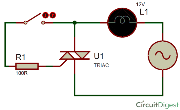
Here we have used the TRIAC to turn On and off an AC load through a push button. The mains power source is then wired to a small bulb through the TRIAC as shown above. When the switch is closed the phase voltage is applied to the gate pin of the TRIAC through the resistor R1. If this gate voltage is above the gate threshold voltage then a current flows through the gate pin, which will be greater than the gate threshold current.
At this condition the TRIAC enters forward bias and the load current will flow though the Bulb. If the loads consumes enough current the TRIAC enter into latching state. But since this is an AC power source the voltage will reach zero for every half cycle and thus the current will also reach zero momentarily. Hence latching is not possible in this circuit and the TRIAC will turn off as soon as the switch is opened and no commutation circuit is required here. This type of commutation of TRIAC is called as natural commutation. Now let us build this circuit on a breadboard using the BT136 TRIAC and check how it works.
High caution is needed while working with AC power supplies the operating voltage is stepped down for safety purpose The standard AC power of 230V 50Hz (In India) is stepped down to 12V 50Hz using a transformer. A small bulb is connected as a load. The experimental set-up looks like this below when completed.
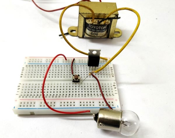
When the button is pressed the gate pin receives the gate voltage and thus the TRIAC is turned ON. The bulb will glow as long as the button is held pressed. Once the button is released, the TRIAC will be in latched state, but since the input voltage is AC the current though the TRIAC will go below the holding current and thus the TRIAC will turn off, the complete working can also be found in the video given at the end of this tutorial.
TRIAC control using Microcontrollers
When TRIACs are used as light dimmers or for Phase control application, the gate pulse that is supplied to the gate pin has to be controlled using a microcontroller. In that case the gate pin will also be isolated using an opto-coupler. The circuit diagram for the same is shown below.

To control the TRIAC using a 5V/3.3V signal we will use an opto-coupler like the MOC3021 which has a TRIAC inside it. This TRIAC can be triggered by 5V/3.3V through the Light Emitting Diode. Normally a PWM signal will be applied to the 1st pin of MOC3021 and the frequency and duty cycle of the PWM signal will be varied to get the desired output. This type of circuit is normally used for Lamp brightness control or motor speed control.
Rate Effect – Snubber Circuits
All TRIACs suffer from a problem called Rate Effect. That is when the MT1 terminal is subjected to sharp increase in voltage due to switching noise or transients or surges the TRIAC miss-interrupts it as a switching signal and turns ON automatically. This is because of the internal capacitance of present between the terminals MT1 and MT2.
The easiest way to overcome this problem is by using a Snubber circuit. In the above circuit, the Resistor R2 (50R) and the Capacitor C1 (10nF) together forms an RC network which acts as a Snubber circuit. Any peak voltages supplied to MT1 will be observed by this RC network.
Backlash Effect
Another common problem that will be faced by designers while using TRIAC is the Backlash effect. This problem occurs when a potentiometer is used for controlling the gate voltage of the TRIAC. When the POT is turned to minimum value, no voltage will be applied to gate pin and thus the Load will be turned off. But when the POT is turned to maximum value the TRIAC will not switch on because of the capacitance effect between the pins MT1 and MT2, this capacitor should find a path to discharge else it will not allow the TRIAC o turn ON. This effect is called as the Backlash effect. This problem can be rectified by simply introducing a resistor in series with switching circuit to provide a path for the capacitor to discharge.
Radio Frequency Interference (RFI) and TRIACs
TRIAC switching circuits are more prone to Radio Frequency interference (EFI) because when the load is turned on, the current raises form 0A to maximum value all of a sudden thus creating a burst of electric pulses which causes Radio Frequency Interface. The larger the load current is the worse will be the interference. Using Suppressor circuits like an LC suppressor will solve this problem.
TRIAC – Limitations
When required to switch AC waveforms in both the directions obviously TRIAC will be the first choice since it is the only bi-directional power electronic switch. It acts just like two SCRs connected in back to back fashion and also share the same properties. Although while designing circuits using TRIAC the following limitations must be considered
- The TRIAC has two SCR structures inside it, one conducts during positive half and the other during negative half. But, they do not trigger symmetrically causing difference in the positive and negative half cycle of the output
- Also since the switching is not symmetrical, it leads to high level harmonics which will induce noise in the circuit.
- This harmonics problem will also lead to Electro Magnetic Interference (EMI)
- While using inductive loads, there is a huge risk of inrush current flowing towards the source, hence it should be ensured that TRIAC is turned off completely and the inductive load is discharged safely through an alternate path
