

In general, Thyristors are also switching devices similar to transistors. As we already discussed, Transistors are the tiny electronic components that changed the world. Today we can find them in every electronic device like TVs, mobiles, laptops, calculators, earphones, etc. They are adaptable and versatile, but that doesn’t mean that they can be used in every application. We can use them as amplifying and switching devices, but they cannot handle higher currents. Also, a transistor requires a continuous switching current. So, for all these issues and to overcome these problems, we use Thyristors.
Generally, SCR and Thyristor are used interchangeably, but SCR is a kind of Thyristor. Thyristor includes many types of switches, some of which are SCR (Silicon Controlled Rectifier), GTO (Gate Turn OFF), and IGBT (Insulated Gate Bipolar Transistor), etc. But SCR is the most widely used device, so the word Thyristor has become synonymous with SCR. Simply, SCR is a kind of Thyristor.
Table of Contents
- What is a Thyristor?
- └ Thyristor Main Features
- Thyristor Diagram and Symbol
- └ Thyristor Operating Modes
- Two-Transistor Analogy of Thyristor
- How is a Thyristor different from an MOSFET?
- How is a Thyristor Different from a Transistor?
- V-I Characteristics of Thyristor or SCR
- └ Three Operating Regions
- Triggering Methods of SCR or Thyristor
What is a Thyristor?
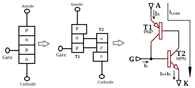
SCR or Thyristor is a four-layered, three-junction semiconductor switching device. It has three terminals: anode, cathode, and gate. A thyristor is also a unidirectional device like a diode, which means it allows current only in one direction. It consists of three PN junctions in series, as it has four layers. The GATE terminal is used to trigger the SCR by providing a small voltage to this terminal, which we also call the gate triggering method, to turn ON the SCR.
Thyristor Main Features
- Four semiconductor layers. (P-N-P-N configuration)
- Three terminals: Anode, Cathode, Gate
- Allows unidirectional current flow (as a diode).
- Latching behaviour. Once it is triggered, it remains ON.
- Rated for high power (kilowatts, not watts like transistors)
Thyristor Diagram and Symbol
The thyristor diagram shows its internal structure and circuit symbol, which are essential for understanding its operation and circuit design.


Thyristor Operating Modes
| Operating Mode | Anode-Cathode | Gate Signal | Current Flow | Application |
| Forward Blocking | Positive | No Signal | Blocked | Waiting state |
| Forward Conducting | Positive | Triggered | Conducting | Power delivery |
| Reverse Blocking | Negative | Any | Blocked | Protection mode |
Two Transistor Analogy of Thyristor
Here, the equivalent circuit of two transistors shows that the base of the PNP transistor T1 is fed by the collector current of the NPN transistor T2, and the collector current of transistor T1 feeds the base of transistor T2. The two transistor analogy provides an excellent way to understand thyristor operation by representing it as two interconnected transistors - one PNP and one NPN. Hence, the conduction of both transistors depends on each other. So, until one of the bases of any transistor gets base current, it will not conduct even if the voltage is present at the anode and the cathode. The main difference between the transistor and the Thyristor is that, transistor turns off as the base current is removed, while the Thyristor remains ON just by being triggered it once. For applications like an alarm circuit which need to trigger once and stay ON forever, cannot use a transistor. So, to overcome these problems, we use a Thyristor.
How is a Thyristor different from an MOSFET?
Thyristors and MOSFETs are both electrical switches and are most commonly used. The basic difference between them is that MOSFET switches are voltage-controlled devices and can only switch DC, while Thyristor switches are current-controlled devices and can switch both DC and AC. The thyristor vs MOSFET comparison reveals fundamental differences in control methods, power handling, and application areas.
There are some more differences between Thyristor and MOSFET are given below in the table:
| Property | Thyristor | MOSFET |
| Thermal Run away | Yes | No |
| Temperature sensitivity | less | high |
| Type | High voltage high current device | High voltage medium current device |
Turning off | Separate switching circuit is required | Not required |
Turning On | Single pulse required | No continuous supply is required except during turning On and Off |
Switching speed | low | high |
| Resistive input impedance | low | high |
Controlling | Current controlled device | Voltage controlled device |
How is a Thyristor Different from a Transistor?
Thyristors and transistors are both electrical switches, but the power handling capacity of Thyristors is far better than transistors. Due to having a high rating of Thyristor, given in kilowatts, while of transistor power ranges in watts. A Thyristor is taken as a closed-coupled pair of transistors in analysis. The main difference between the transistor and the Thyristor is that a transistor needs a continuous switching supply to remain ON, but in the case of a Thyristor, we need to trigger it once only, and it remains ON. For applications like an alarm circuit which need to trigger once and stay ON forever, cannot use a transistor. So, to overcome these problems, we use a Thyristor. Understanding thyristor vs transistor differences is crucial for selecting the right component for your application.
There are some more differences between Thyristor and Transistor are given below in the table:
Property | Thyristor | Transistor |
Layer | Four Layers | Three Layers |
Terminals | Anode, Cathode and Gate | Emitter, Collector, and Base |
Operation over voltage and current | Higher | Lower than thyristor |
Turning ON | Just required a gate pulse to turn ON | Required continuous supply of the controlling current |
Internal power loss | Lower than transistor | higher |
V-I Characteristics of Thyristor or SCR
The basic circuit for obtaining Thyristor V-I characteristics is given below. The anode and cathode of the Thyristor are connected to the main supply through the load. The gate and cathode of the Thyristor are fed from a source Es, used to provide gate current from the gate to the cathode.


Three Operating Regions
As per the characteristic diagram, there are three basic modes of SCR: reverse blocking mode, forward blocking mode, and forward conduction mode.
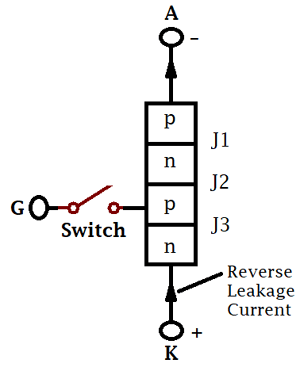
Reverse Blocking Mode:
In this mode, the cathode is made positive with respect to the anode with switch S open. Junctions J1 and J3 are reverse-biased, and J2 is forward-biased. When reverse voltage is applied across the Thyristor (should be less than VBR), the device offers a high impedance in the reverse direction. Therefore, the Thyristor is treated as an open switch in the reverse blocking mode. VBR is the reverse breakdown voltage where the avalanche occurs. If the voltage exceeds VBR may cause damage to the Thyristor.
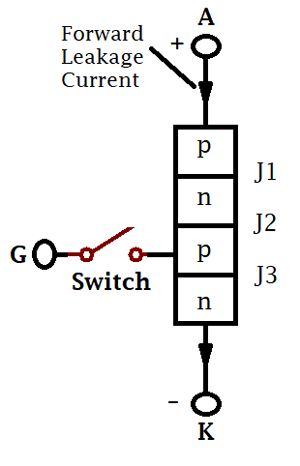
Forward Blocking Mode:
When the anode is made positive with respect to the cathode, with the gate switch open. The thyristor is said to be forward biased, junctions J1 and J3 are forward biased, and J2 is reverse biased, as you can see in the figure. In this mode, a small current flows, called forward leakage current, as the forward leakage current is small and not enough to trigger the SCR. Therefore, SCR is treated as an open switch even in forward blocking mode.
Forward Conduction Mode:
As the forward voltage is increased with the gate circuit remaining open, an avalanche occurs at junction J2, and the SCR comes into conduction mode. We can turn ON the SCR at any moment by giving a positive gate pulse between the gate and cathode or by a forward breakover voltage across the anode and the cathode of the Thyristor.
Triggering Methods of SCR or Thyristor
There are multiple methods to trigger a thyristor into conduction state. Understanding these triggering methods is essential for proper thyristor circuit design. Thyristor circuits are widely used in power electronics for controlling high-power loads efficiently. There are many methods for triggering the SCR, like:
- Forward Voltage Triggering
- Gate Triggering
- dv/dt triggering
- Temperature Triggering
- Light Triggering
Forward Voltage Triggering:
By applying a forward voltage between anode and cathode, while keeping the gate circuit open, junction J2 is reverse-biased. As a result, the formation of a depletion layer occurs across J2. As the forward voltage increases, a stage comes when the depletion layer vanishes, and J2 is said to have Avalanche Breakdown. Hence, the Thyristor comes into the conduction state. The voltage at which the avalanche occurs is called as forward breakover voltage, VBO.
Gate Triggering:
It is one of the most common, reliable and efficient ways to turn ON the Thyristor or SCR. In gate triggering, to turn ON an SCR, a positive voltage is applied between the gate and the cathode, which gives rise to the gate current and the charge gets injected into the inner P layer and forward breakover occurs. As the gate current increases, the forward breakover voltage increases.
As shown in the figure, there are three junctions in an SCR. Now, for turning ON the SCR, the junction J2 should break. By using the gate triggering method, as the gate pulse is applied, the junction J2 breaks, junctions J1 and J2 get forward biased, or the SCR comes into conduction state. Hence, it allows the current to flow through the anode to the cathode.
As per the two transistor model, when the anode is made positive with respect to the cathode. Current will not flow through the anode to the cathode until the gate pin is triggered. When current flows into the gate pin, it turns ON the lower transistor. As the lower transistor conducts, it turns ON the upper transistor. This is a kind of internal positive feedback, so by providing a pulse at the gate for one time, it made the Thyristor stay in the ON condition. When both transistor turns ON, current starts conducting through the anode to the cathode. This state is known as forward conducting, and this is how a transistor “latches” or stays permanently ON. For turning OFF the SCR, you cannot turn it off just by removing gate current; at this state, the Thyristor becomes independent of gate current. So, to turn OFF, you have to make a switching OFF circuit.
dv/dt Triggering:
In a reverse-biased junction, J2 acquires the characteristics of a capacitor because of the presence of charge across the junction, which means junction J2 behaves like a capacitance. If the forward voltage is applied suddenly, a charging current through the junction capacitance Cj leads to turns ON the SCR.
The charging current iC is given by;
iC = dQ/dt = d(Cj*Va) / dt                  (where, Va is forward voltage appears across junction J2)
iC = (Cj * dVa /dt) + (Va* dCj / dt )
as the junction capacitance is nearly constant, dCj / dt is zero, then
iC = Cj dVa / dt
Therefore, if the rate of rise of forward voltage dVa /dt is high, the charging current iC would be higher. Here, the charging current plays the role of gate current to turn ON the SCR even when the gate signal is zero.
Temperature Triggering:
When the Thyristor is in forward blocking mode, most of the applied voltage collects over the junction J2; this voltage is associated with some leakage current. This increases the temperature of the junction J2. So, with the increase in temperature, the depletion layer decreases, and at some high temperature (within the safe limit), the depletion layer breaks and the SCR turns to the ON state.
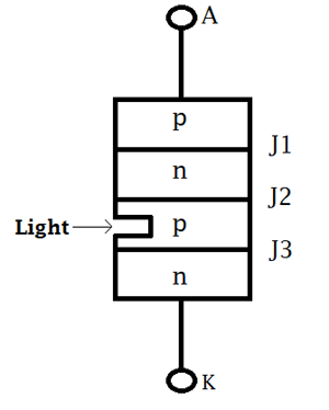
Light Triggering:
For triggering an SCR with light, a recess (or hollow) is made inner p-layer as shown in the figure below. The beam of light of a particular wavelength is directed by optical fibres for irradiation. As the intensity of the light exceeds a certain value, SCR turn ON. This type of SCR is called Light Activated SCR (LASCR). Sometimes, these SCR are triggered using both the light source and gate signal in combination. High gate current and lower light intensity are required to turn ON the SCR.
LASCR or Light-triggered SCR are used in HVDC (High Voltage Direct Current) transmission systems.
Frequently Asked Questions on Thyristor Circuit
⇥ How does a thyristor function in simple terms?
A thyristor is like an electrically controlled switch - a trigger pulse (in the form of a small current to the gate terminal) can be applied to turn it ON. When it is ON, we can have a large current flowing through it. If we turn a thyristor ON, it remains ON even after the gate connection is removed.
⇥ What are the three terminals of a thyristor?
A thyristor has three terminals or electrodes: Anode (the positive terminal), Cathode (the negative terminal), and Gate (the control terminal). The gate terminal is the connection for the trigger signal to turn the thyristor ON.
⇥ Why can't we turn OFF a thyristor using the gate?
Once we trigger the thyristor ON, it establishes a positive feedback loop between its internal transistor structure and the gate loses control. The thyristor can only be turned OFF by dropping the current below the holding current or by applying a reverse voltage.
⇥ When should I use a thyristor instead of an MOSFET?
Use thyristors in high-power AC applications when you require latching behaviour, or when you are only implementing simple ON/OFF functionality. Use MOSFET when you need quick switching, precise control capabilities, or require easy turn-off.
⇥ What is the forward breakover voltage in a thyristor?
Forward breakover voltage (VBO) is the voltage at which the thyristor will turn ON automatically; this occurs without a gate signal, due to avalanche breakdown occurring at junction J2. Forward breakover voltage will typically range from hundreds to thousands of volts.
⇥ How do you protect thyristors from dv/dt triggering?
You will protect thyristor from dv/dt triggering by limiting the rate of voltage change through:
- snubber circuits (RC networks)
- properly designed gate drive circuit
- having controlled voltage rise rates
Snubber circuits serve the purpose of limiting the rate of voltage change across the device.
⇥ What are the applications of thyristor circuits?
Thyristor circuits are used in:
- AC power control applications (Dimmers, motor drives)
- Rectifiers (Battery chargers, DC supplies)
- Protection circuits (crowbar protection)
- Switching applications (static switches, inverters) for high-power applications.
Innovative Applications of Circuit Ideas
Explore how this Circuit has been utilised in various practical applications through the links provided.

How to build a Simple IR Transmitter and Receiver Circuit using a 555 Timer?
Here in our circuit, we are building an IR remote and its receiver. We are using an IR LED as a transmitter and a TSOP1738 as an IR receiver.

Design a Voltage Controlled Current Source Circuit using an Op-Amp
This comprehensive guide demonstrates how to design and build a voltage-controlled current source using an op amp with practical examples. This type of voltage-controlled current source circuit is also called a current servo.

Full Subtractor Circuit and Its Construction
So, in the case of the Full Subtractor Circuit, we have three inputs: A, which is the minuend, B, which is the subtrahend and Borrow In. On the other side, we get two final outputs, Diff (Difference) and Borrow out.

This should have been spelled checked, and checked for proper use of certain words. it made for slow reading, trying to guess what you meant to say.. I many cases, I knew what you meant to say, because i knew the topic you are discussing. The information could have been organized better , as well. If you can't fix it because English is your second language, ask a friend to edit it for you.