
 using MSP430G2: Controlling Brightness of LED")
This tutorial is a part of series of MSP430G2 LaunchPad tutorials in which we are learning to use the MSP430G2 LaunchPad from Texas Instruments. So far we have learnt the basics of the board and have covered how to read analog voltage, interface LCD with MSP430G2 etc. Now we proceed with the next step of learning about PWM in MSP430G2. We will do that by controlling the brightness of a LED by varying the potentiometer. So the potentiometer will be attached to an analog pin of the MSP430 to read its analog voltage, hence it is recommended to know go through the ADC tutorial before proceeding.
What is a PWM Signal?
Pulse Width Modulation (PWM) is a digital signal which is most commonly used in control circuitry. This signal is set high (3.3v) and low (0v) in a predefined time and speed. The time during which the signal stays high is called the “on time” and the time during which the signal stays low is called the “off time”. There are two important parameters for a PWM as discussed below:
Duty cycle of the PWM:
The percentage of time in which the PWM signal remains HIGH (on time) is called as duty cycle. If the signal is always ON it is in 100% duty cycle and if it is always off it is 0% duty cycle.
Duty Cycle =Turn ON time/ (Turn ON time + Turn OFF time)
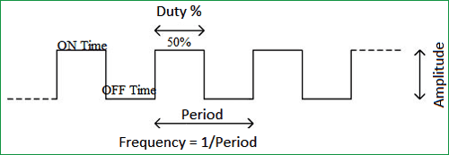
Frequency of a PWM:
The frequency of a PWM signal determines how fast a PWM completes one period. One Period is complete ON and OFF of a PWM signal as shown in the above figure. In our tutorial the frequency be 500Hz as it is the default value set by the Energia IDE.
There is plethora of applications for PWM signals in real time, but to give you an idea the PWM signal can be used to control servo Motors and can also be converted to Analog voltage which can control the brightness of the brightness of an LED. Let’s learn a bit about how that could be done.
Here are few PWM examples with other Microcontroller:
- Generating PWM using PIC Microcontroller with MPLAB and XC8
- Servo Motor Control with Raspberry Pi
- Arduino Based LED Dimmer using PWM
Check all the PWM related projects here.
How to convert PWM signal to Analog voltage?
To PWM signals to Analog voltage we can use a circuit called RC filter. This is a simple and most commonly used circuit for this purpose. The circuit just includes a Resistor and a capacitor in series as shown in the below circuit.
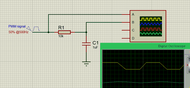
So what basically happens here is that when the when the PWM signal is high the capacitor charges up though the resistor and when the PWM signal goes low the capacitor discharges through the stored charge. This way we will always have a constant voltage at the output which will be proportional to the PWM duty cycle.
In the graph shown above, the Yellow coloured one is the PWM signal and the blue colour one is the output analog voltage. As you can see the output wave will not be a pure DC wave but it should very well work for our application. If you need pure DC wave for other type of application you should design a switching circuit.
Circuit Diagram:
 using MSP430G2 and Controlling Brightness of LED")
The circuit diagram is pretty simple; it just has a potentiometer and a Resistor and capacitor to form a RC circuit and the Led itself. The potentiometer is used to provide an analog voltage based on which the PWM signal duty cycle can be controlled. The output of the pot is connected to Pin P1.0 which can read analog voltages. Then we have to produce a PWM signal, which can be done by using the pin P1.2, this PWM signal is then sent to the RC filter circuit to convert the PWM signal into Analog Voltage which is then given to the LED.
It is very important to understand that not all pin on the MSP board can read analog voltage or can generate PWM pins. The specific pins which can do the specific tasks are shown in the figure below. Always use this as a guidance to select your pins for programming.

Assemble the complete circuit as shown above, you can use a breadboard and few jumper wires and easily make the connections. Once the connections are done my board looked like as shown below.
Programming the MSP for PWM signal:
Once the hardware is ready we can start with our programming. The first thing in a program is to declare the pins that we are going to use. Here we are going to use the pin number 4 (P1.2) as our output pin since it has the ability to generate PWM. So we create a variable and assign the pin name so that it’s easy to refer to it later in the program. Complete program is given at the end.
int PWMpin = 4; //We are using the 4th pin on the MSP module as PWM pin
Next we come into the setup function. Whatever code is written here will be executed only once, here we declare that we are using this 4th pin as an output pin since PWM is output functionality. Note that we have used the variable PWMpin here instead of the number 4 so that the code looks more meaningful
void setup() {

pinMode(PWMpin,OUTPUT); //The PEMpin is set as Outptut

}
Finally we get into the loop function. Whatever we write here gets executed again and again. In this program we have to read the analog voltage and generate a PWM signal accordingly and this has to happen again and again. So first let’s start by reading the analog voltage from the pin A0 since we have connected to potentiometer to it.
Here we are reading the value using the AanalogRead function, this function will return a value from 0-1024 based on the value of voltage applied to the pin. We then store this value to a variable called “val” as shown below
int val = analogRead(A0); // read the ADC value from pin A0
We have to convert the values of 0 to 1024 from the ADC to values of 0 to 255 to give it to the PWM function. Why should we convert this? I will tell that shortly, but for now just remember we have to convert. To convert one set of values to another set of values Energia has a map function similar to Arduino. So we convert the values of 0-1204 to 0-255 and save it back in the variable “val”.
val = map(val, 0, 1023, 0, 255); //The ADC will give a value of 0-1023 convert it to 0-255
Now we have a variable value of 0-255 based on the position of the potentiometer. All we have to do is, use this value on the PWM pin this can be done using the following line.
analogWrite(PWMpin,val); //Write that value to the PWM pin.
Let’s get back to the question why 0-255 is written to the PWM pin. This value 0-255 decides the duty cycle of the PWM signal. For example if the value of signal is 0 then it means the duty cycle is 0% for 127 it is 50% and for 255 it is 100% just like what is shown and explained at the top of this article.
Controlling Brightness of LED with PWM:
Once you have understood the hardware and code, it is time to have some fun with the working of the circuit. Upload the code to the MSP430G2 board and turn the potentiometer knob. As you turn the knob the voltage on pin 2 will vary which will be read by the microcontroller and according to the voltage the PWM signals will be generated on pin 4. The greater the voltage, the greater will be the duty cycle and vice versa.
This PWM signal then gets converted into analog voltage to glow an LED. The brightness of the LED is directly proportional to the PWM signal duty cycle. Apart from the LED on the breadboard you can also notice the smd LED (red colour) varying its brightness similar to the breadboard led. This is LED is also connected to the same pin, but it does not have a RC network so it is actually flickering very fast. You can shake the board in a dark room to check its flickering nature. The complete working can also be seen in the video below.
That is all for now folks, we have learnt how to use PWM signals on MSP430G2 board, in our next tutorial we will learn how easy it is to control a servo motor using the same PWM signals. If you have any doubts post them on the comment section below or on the forums for technical help.
Complete Project Code
int PWMpin = 4; //We are using the 4th pin on the MSP module as PWM pin
void setup() {

pinMode(PWMpin,OUTPUT); //The PEMpin is set as Outptut

}

void loop() {

 int val = analogRead(A0);    // read the ADC value from pin A0

 val = map(val, 0, 1023, 0, 255);  //The ADC will give a value of 0-1023 convert it to 0-255

 analogWrite(PWMpin,val);  //Write that value to the PWM pin.

}

how to make the frequency to 50 khz