
Resistors

|
New High-Voltage Thick Film Chip Resistors Reduce Component Counts and Save Board Space Vishay Intertechnology has released the RCV-AT e3 series of AEC-Q200 qualified thick film chip resistors with operating voltages up to 3 kV in the 2010 and 2512 case sizes. The new resistors in the series enable designers to save board space in inverters for electric (EV) and hybrid electric (HEV) vehicles, on-board chargers, and DC/DC converters while lowering… |

|
Simple MOSFET Switching Circuit – How to turn on / turn off N-Channel and P-channel MOSFETs A MOSFET is a type of transistor that uses an electric field to control current flow, and is widely used in switching and amplification circuits. MOSFET stands for Metal Oxide Semiconductor Field Effect Transistor, which has a gate. For simplicity, you can imagine this gate like a water tap. You rotate the tap counter-clockwise the water starts flowing out of the tap.… |

|
Astable Multivibrator Circuit Using Op-amp The multivibrator circuit is very popular and useful in the field of electronics, and it’s the most basic circuit that you will know about while learning basic electronics. The multivibrator circuit can be divided into two categories: the first one is known as the monostable multivibrator, and the second one is known as the astable multivibrator. But in this project, we will… |

|
Zero-Crossing Detector Circuit A zero-crossing detector circuit is a useful application of an op-amp as a comparator. This electronic circuit precisely identifies when an AC waveform transitions through zero voltage, tracking the changes in the sine waveform from positive to negative or vice versa while it crosses zero voltage. It can also be used as a square wave generator. They have many… |
|
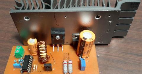
Designing a High Power, High Efficiency Boost Converter using TL494 In this article, we are going to design a TL494 Boost converter, and calculate and test a high-efficiency boost converter circuit based on the popular TL494 IC, which has a minimum supply voltage of 7V and a maximum of 40V, and as we are using the IRFP250 MOSFET as a switch, this circuit can handle a maximum current of 19Amps, theoretically (Limited by Inductor… |

|
Simple Square wave to Sine Wave Converter A square wave to Sine wave converter circuit is an important analog circuit that converts square waveforms to sine waveforms. It has a broad spectrum of applications in many different areas of electronics, such as mathematical operations, acoustics, audio applications, inverters, power sources, function generators, etc. In this project, we will… |

|
Half Wave and Full Wave Precision Rectifier Circuit using Op-Amp A rectifier is a circuit that converts alternating current (AC) to Direct current (DC). An alternating current always changes its direction over time, but a direct current flows continuously in one direction. In a typical rectifier circuit, we use diodes to rectify AC to DC. But this rectification method can only be used if the input voltage to the circuit is greater than… |

|
Impedance Matching Filter Circuit Design – LC, L and PI Filters In the previous article, we discussed the basics of impedance matching and how to use an impedance matching transformer. Apart from using an impedance matching transformer, designers can also use Impedance Filter circuits at the output of an RF amplifier which can double up as a filtering circuit and also as an impedance matching circuit. There are many types of filter… |

|
Introduction to Impedance Matching and How to use an Impedance Matching Transformer for your Design If you are an RF Design Engineer or anyone who has worked with Wireless Radios, the term “Impedance Matching” should have struck you more than once. The term is crucial because it directly affects the transmission power and thus the range of our Radio modules. This article aims to help you understand what Impedance Matching is from the basics and will also help you to design… |

|
Superheterodyne AM Receiver - Working with Block Diagram and Schematics A superheterodyne receiver uses signal mixing to convert the input radio signal into a steady intermediate frequency (IF) that can be worked with more easily than the original radio signal, which has a different frequency, depending on the broadcasting station. The IF signal is then amplified by a strip of IF amplifiers and then fed into a detector that outputs the audio… |
|
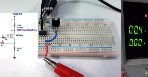
Design a Voltage Controlled Current Source Circuit using Op-Amp In a voltage-controlled current source circuit, as the name implies, a small amount of voltage across the input will proportionally control the current flow across the output loads. This current source circuit using an op amp is commonly used in electronics to drive current-controlled devices like BJT, SCR, etc. We know that in a BJT, the current flowing through the base of… |

|
IoT Based Smart Reminder System Have you ever set an important reminder on your phone only to miss it because the device was in silent mode, left in another room, or buried under tons of notifications? While smartphones have made reminders convenient, they are not always used in every situation, especially for elderly people, students, or professionals with busy schedules.To solve this problem, we… |