
A superheterodyne receiver uses signal mixing to convert the input radio signal into a steady intermediate frequency (IF) that can be worked with more easily than the original radio signal, which has a different frequency, depending on the broadcasting station. The IF signal is then amplified by a strip of IF amplifiers and then fed into a detector that outputs the audio signal into an audio amplifier that powers the speaker. In this article, we will learn about the working of a Superheterodyne AM receiver or superhet for short, with the help of a block diagram.
Most AM receivers found today are of the superheterodyne type because they allow for the use of high selectivity filters in their Intermediate Frequency (IF) stages, and they have high sensitivity (internal ferrite rod antennas can be used) due to the filters in the IF stage, which helps them in getting rid of unwanted RF signals. Also, the IF amplifier strip provides high gain, a good, strong signal response because of the use of automatic gain control in amplifiers and ease of operation (only controls volume, power switch, and the tuning knob).
Table of Contents
Superheterodyne AM Receiver Quick Reference
| Component | Function | Frequency Range |
| RF Filter & Antenna | Signal Reception & Filtering | 530-1700 kHz (AM Band) |
| Local Oscillator | Frequency Generation | 985-2155 kHz |
| Mixer | Frequency Conversion | All frequencies to 455 kHz IF |
| IF Amplifiers | Signal Amplification | 455 kHz (Standard IF) |
| Detector | Demodulation | 20 Hz - 5 kHz (Audio) |
What is a Superheterodyne AM Receiver?
A superheterodyne AM receiver, commonly termed a superhet, is by far the most widely used radio receiver design. It converts incoming radio frequency (RF) signals to a fixed intermediate frequency (IF) for easier processing. Because of the superheterodyne receiver working principle, it is a superior receiver design to AM radio receivers that may offer some advantages in selectivity, sensitivity and stability.
A superheterodyne AM receiver can convert the input radio signal into a constant intermediate frequency (IF) via signal mixing, which can be processed more consistently than the original variable-frequency radio signal. The superhet architecture is now almost uniformly chosen to be the design of choice because most of its radio reception performance characteristics are excellent and critical to operational quality.
Key Advantages of Superheterodyne AM Receivers
» Proper Selectivity: The IF filters have proper adjacent channel rejection.
» Proper Sensitivity: IF amplification allows for multiple weak signal amplifications in stages.
» Proper Function: Given the IF frequency, RF signal amplification will be proper and consistent.
» Proper Function: An automatic gain control feature will keep output levels constant.
» Low Cost: (vol, tuning, power) Superhet designs are relatively simple in their controls.
» Small Antenna: Small internal ferrite rod antennas work well.
Superheterodyne AM Receiver Block Diagram
To understand how it works, let’s take a look at the Superheterodyne AM Receiver Block Diagram, which is shown below.
Superheterodyne Receiver Working Principle
A superheterodyne receiver operates under the principle of heterodyning, which is frequency translation. Here is a description of how the process happens.
1. Reception of Signals: The RF antenna receives the broadcast signals.
2. Mixing Frequencies: The local oscillator mixes with the incoming RF at the receiver.
3. Generating an Intermediate Frequency: The mixing which has taken place will produce a fixed intermediate frequency of 455 kHz when the RF and local oscillator signals are combined.
4. Amplifying: There are several stages of intermediate frequency amplification.
5. Detection: The demodulator will remove the audio carrier.
Detailed Analysis of Superheterodyne AM Receiver Components
As you can see, the block diagram has 11 different stages, each stage has a specific function, which is explained below
- RF Filter: The first block is the ferrite rod antenna coil and variable capacitor combo, that serves two purposes - RF is induced into the coil and the parallel capacitor controls the resonant frequency of it, as ferrite antennas receive the best when the resonant frequency of the coil and capacitor is equal to the station's carrier frequency – this way it acts as an input filter of the receiver.
- Heterodyne Local Oscillator: The second block is the heterodyne, also known as the local oscillator (LO). The frequency of the local oscillator is set, so either the sum or the difference of the RF signal’s frequency and the LO’s frequency is equal to the IF used in the receiver (usually around 455 kHz).
- Mixer: The third block is the mixer, where the RF signal and the LO signal are fed to the mixer to produce the desired IF. Mixers found in common AM receivers output the sum, the difference of the LO and RF’s frequencies and the LO and RF signals themselves. Most often in simple transistor radios, the heterodyne and the mixer are made using one transistor. In higher-quality receivers and those that use dedicated integrated circuits, such as the TCA440, these stages are separate, allowing for more sensitive reception due to the mixer outputting only the sum and difference frequencies. In one transistor LO-mixers, the transistor operates as a common-base Armstrong oscillator, and the RF taken from a coil wound on the ferrite rod, separate from the resonant circuit’s coil, is fed to the base. At frequencies different from the resonant frequency of the antenna resonant circuit, it presents low impedance, so the base stays grounded for the LO signal but not for the input signal, due to the antenna circuit being of a parallel resonant type (low impedance at frequencies different from resonance, almost infinite impedance at the resonant frequency).
- First IF Filter: The fourth block is the first IF filter. In most AM receivers, it is a resonant circuit placed in the collector of the mixer transistor with the resonant frequency equal to the IF frequency. Its purpose is to filter off all signals with a frequency different from the IF frequency because those signals are unwanted mixing products and don’t carry the audio signal of the station we want to listen to.
- First IF Amplifier: The fifth block is the first IF amplifier. Gains of 50 to 100 in each IF stage are common. If the gain is too high, distortion can take place, and if the gain is too high, IF filters are too close to each other and not properly shielded, parasitic oscillation can take place. The amplifier is controlled by AGC (Automatic Gain Control) voltage from the demodulator. AGC lowers the gain of the stage, causing the output signal to be roughly the same, regardless of the input signal amplitude. In transistor AM receivers, the AGC signal is most often fed to the base and has a negative voltage, in NPN transistors, pulling the base bias voltage lower, which reduces gain.
- Second IF Filter: The sixth block is the second IF filter, just like the first one, it is a resonant circuit placed in the collector of the transistor. It only lets signals of the IF frequency – improving selectivity.
- Second IF Amplifier: The seventh block is the second IF amplifier, which is practically the same as the first IF amp, except it is not controlled by AGC, as having too many AGC-controlled stages increases distortion.
- Third IF Filter: the eighth block is the third IF filter, just like the first and the second one is a resonant circuit placed in the collector of the transistor. It only lets signals of the IF frequency – improving selectivity. It feeds the IF signal to the detector.
- Detector: The ninth block is the detector, usually in the form of a germanium diode or a diode-connected transistor. It demodulates AM by rectifying the IF. On its output, there is a strong IF ripple component that is filtered out by a resistor-capacitor low-pass filter, so only the AF component remains; it is fed to the audio amp. The audio signal is further filtered to provide the AGC voltage, like in a regular DC power supply.
- Audio Amplifier: The tenth block is the audio amplifier; it amplifies the audio signal and passes it to the speaker. Between the detector and the audio amplifier, a volume control potentiometer is used.
- Speaker: The last block is the speaker (usually 8 ohms, 0.5W) that outputs audio to the user. The speaker is sometimes connected to the audio amplifier through a headphone jack that disconnects the speaker when headphones are plugged in.
Superheterodyne AM Receiver Circuit Analysis
Now, we know the basic functionality of a Superheterodyne Receiver. Let’s take a look at a typical circuit diagram of a Superheterodyne Receiver. Let's examine a practical superheterodyne receiver circuit implementation using discrete transistors. The circuit below is an example of a simple transistor radio circuit constructed using the TR830 super-sensitive transistor from Sony.

The circuit might appear complicated at first glance, but if we compare it with the block diagram that we learned earlier, it becomes simple. So, let’s split each section of the circuit to explain its working.
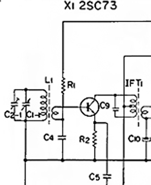
Antenna and mixer – L1 is the ferrite rod antenna, which forms a resonant circuit with C2-1 and C1-1 variable capacitors in parallel. The secondary winding couples into the base of mixer transistor X1. The LO signal is fed to the emitter from the LO by C5. Output IF is taken from the collector by IFT1, the coil is tapped on the collector in an auto-transformer fashion, because if the resonant circuit was connected directly between the collector and Vcc, the transistor would load the circuit considerably, and the bandwidth would be too high – around 200kHz. This tapping reduces the bandwidth to 30kHz.
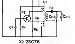
LO – Standard common-base Armstrong oscillator, C1-2 is tuned alongside C1-1 so that the difference of the LO and RF frequencies is always 455kHz. The LO frequency is determined by L2 and the total capacitance of C1-2 and C2-2 in series with C8. L2 provides feedback for oscillations from the collector to the emitter. The base is RF grounded.
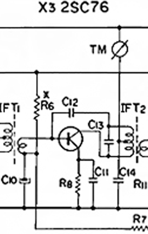
X3 is the first IF amp. To use a transformer to feed the base of a transistor amplifier, we put the secondary between the base and the bias and put a decoupling capacitor between the bias and the transformer secondary to close the circuit for the signal. This is a more efficient solution than feeding the signal through a coupling capacitor to the base, connected directly to bias resistors
TM is a signal strength meter measuring current flowing into the IF amp, as higher input signals cause more current to flow through the IF transformer into the second IF amp, increasing IF amp supply current that the meter measures. C14 filters the supply voltage along with R9 (off-screen), as RF and electric grid hum can be induced into the coil of the TM meter.
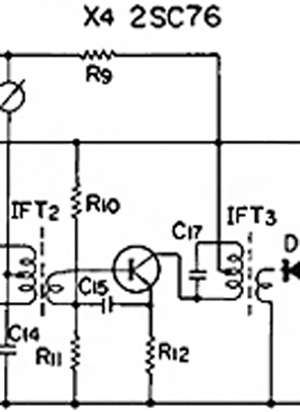
X4 is the second IF amp, bias is fixed, set by R10 and R11, C15 grounds the base for IF signals; it’s connected to the un-decoupled R12 to provide negative feedback in order to decrease distortion, all else is the same as in the first amp.
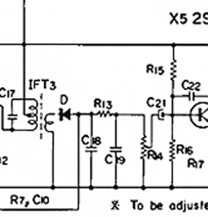
D is the detector. It demodulates the IF and supplies the negative AGC voltage. Germanium diodes are used because of their forward voltage being two times lower than silicon diodes, causing higher receiver sensitivity and lower audio distortion/ R13, C18 and C19 form a PI topology low-pass audio filter, while R7 controls AGC strength and forms a low-pass filter with C10 that filters the AGC voltage from both the IF and the AF signal.
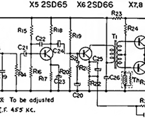
X5 is the audio preamplifier, R4 controls volume, and C22 provides negative feedback at higher frequencies, providing additional low-pass filtering. X6 is the driver of the power stage. S2 and C20 form a tone control circuit – when the switch is pressed, C20 grounds higher audio frequencies, acting as a crude low-pass filter. This was important in early AM radios, as speakers had very bad low-frequency performance and received audio sounded “tinny”. Negative feedback from the output is applied to the emitter circuit of the driver transistor.
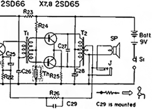
T1 inverts the phase of signals coming to the base of X7 versus the phase at the base of X8. T2 turns the half-wave current pulls of each transistor back to a whole waveform and matches the higher transistor amp impedance (200 ohms) to the 8-ohm speaker. One transistor pulls current when the input signal is at a positive waveform, and the other one when the waveform is negative. R26 and C29 provide negative feedback, reducing distortion and improving audio quality and frequency response. J and SP are connected in a way that switches the speaker off when headphones are plugged in. The audio amp provides around 100mW of power, sufficient for an entire room.
Troubleshooting Common Issues and Solutions
| Problem | Possible Causes | Solution |
| No Reception | Dead oscillator, broken antenna | Check LO operation, antenna continuity |
| Weak Signals | Poor AGC, IF misalignment | Adjust IF transformers, check AGC voltage |
| Poor Selectivity | Wide IF filters, oscillator drift | Realign IF stages, stabilize oscillator |
| Distorted Audio | Overdriven IF stages, bad detector | Reduce IF gain, replace detector diode |
Due to its superior performance and other parameters, the superheterodyne AM receiver is still the preferred method for broadcast reception. Anyone working in the area of radio frequency electronics would benefit from an understanding of the superheterodyne AM radio receiver block diagram. Whether you are designing a simple crystal radio or designing advanced communications equipment, the principles shown in this superheterodyne receiver circuit guide are the first principles of good RF design.
Frequently Asked Questions - Superheterodyne AM receiver
⇥ 1. What is the major benefit of superheterodyne receivers?
All frequencies are converted to a single, fixed intermediate frequency (455kHz) that is used for optimisation of filtering and fürther amplification. This feature, which is unique to superheterodyne receivers, results in better selectivity, sensitivity and stability that is impossible to achieve in direct conversion or tuned radio frequency receivers.
⇥ 2. Why is 455 kHz chosen as the intermediate frequency for AM receivers?
455 kHz was chosen as the standard because it provides good image rejection with reasonable reference plane component size and cost. 455 kHz is far enough above the AM band where there will not be any interference (530-1700 kHz), but low enough to allow reasonable transformer designs and offer transistor sparking gain stability.
⇥ 3. How does AGC work in a superheterodyne AM receiver?
AGC (Automatic Gain Control) samples the detector output signal and produces a negative voltage in relation to signal strength. The superhet detector controls the IF amplifier gain for strong signals and keeps the audio output level consistent through varying (stronger and weaker) signals while preventing overload distortion from the stronger signals.
⇥ 4. What causes image frequency interference in superheterodyne receivers?
Image frequency interference occurs when any signal above or below the local oscillator frequency at LO±IF reaches the mixer, where it is again translated in frequency with any other input signal. For example, if tuning to a frequency of 1000 kHz with a local oscillator of 1455 kHz, a signal at 1910 kHz will also produce an intermediate frequency signal of 455 kHz. Using adequate RF filters on the input side of the mixer will eliminate unwanted image responses.
⇥ 5. Do superheterodyne receivers work without an external antenna?
Yes! Most are AM superheterodyne receivers that have internal ferrite rod antennas. Just like a car radio, these small, directional antennas have enough sensitivity to pick up local AM stations and some radio stations in your area. Most users would benefit from an external antenna for improved reception of weak or faraway stations.
⇥ 6. What is the difference between single conversion and double conversion superheterodyne receivers?
Single conversion superheterodyne receivers use one IF frequency (455 kHz for AM). Double conversion superheterodyne receivers use a second IF stage (generally between 50 - 100 kHz) to improve selectivity and frequency image rejection. This approach is used in high-performance receivers and shortwave radios that require better performance.
Hands-on Receiver Design Projects
Our earlier projects demonstrate practical applications of receivers. Browse through the links to see innovative implementations of receivers in our past work.

Simple DIY FM Receiver Circuits on the Internet - Do They Really Work?
So in this tutorial, we did just that by building a few circuits on a piece of perf board and testing each circuit to see if it was working and what can be done to improve this, and in the end, we will let you know all the details. Building a simple FM receiver circuit from scratch can be both educational and rewarding.

RF Transmitter and Receiver Circuit
Here we will learn the basics of the RF module and how to use it as a standalone RF Transmitter and Receiver. Here, we have explained the RF Transmitter and Receiver Circuit by controlling the LEDs wirelessly using RF.

How to build a Simple IR Transmitter and Receiver Circuit using a 555 Timer?
TV generally consists of a TSOP1738 as the IR receiver, which senses modulated IR pulses and converts them into an electrical signal. Here in our circuit, we are building an IR remote and its receiver. We are using an IR LED as a transmitter and a TSOP1738 as an IR receiver.

Midterm Exam:
Using a pencil and ruler, illustrate manually and explain the following circuits:
• Superheterodyne AM Receiver
• Block diagram of a typical transistor AM superheterodyne receiver
• Simple transistor radio circuit (model TR-830)
• Antenna and mixer