

A rectifier is a circuit that converts alternating current (AC) to Direct current (DC). An alternating current always changes its direction over time, but a direct current flows continuously in one direction. In a typical rectifier circuit, we use diodes to rectify AC to DC. But this rectification method can only be used if the input voltage to the circuit is greater than the forward voltage of the diode, which is typically 0.7V. We previously explained diode-based half-wave rectifier and full-wave rectifier circuit.
To overcome this issue, the Precision Rectifier Circuit was introduced. The precision rectifier is another rectifier that converts AC to DC, but in a Precision rectifier using op amp to compensate for the voltage drop across the diode, that is why we are not losing the 0.6V or 0.7V voltage drop across the diode, also the circuit can be constructed to have some gain at the output of the amplifier as well.
So, in this tutorial, I am going to show you how you can build, test, apply, and debug a precision rectifier circuit using op-amp. Alongside that, I will be discussing some pros and cons of this circuit as well. So, without further ado, let's get started.
Table of Contents
- What is a Precision Rectifier Circuit Using Op-Amp?
- Precision Rectifier Circuit Types
- Half Wave Precision Rectifier Circuit Design
- Working Principle of Half Wave Rectifier Using Op-Amp
- Practical Implementation and Common Issues
- The Modified Precision Rectifier Circuit
- └ Improved Half-Wave Precision Rectifier Design
- Precision Full Wave Rectifier using Op-Amp
- Full Wave Precision Rectifier Circuit Analysis
- Components Required for Full Wave Precision Rectifier
- Circuit Diagrams and Schematic
- Performance Enhancement and Troubleshooting
- Frequently Asked Questions
- More Op-Amp Projects
What is a Precision Rectifier Circuit Using Op-Amp?
Before we study the precision rectifier circuit with op-amp, it is important to review the essential principles of the rectifier circuit.

The above figure shows the characteristics of an ideal rectifier circuit with its transfer characteristics. This implies that when the input signal is negative, the output will be zero volts, and when the input signal is positive, the output will follow the input signal.

The above figure shows a practical rectifier circuit with its transfer characteristics. In a practical rectifier circuit, the output waveform will be 0.7 volts less than the applied input voltage, and the transfer characteristic will look like the figure shown in the diagram. At this point, the diode will only conduct if the applied input signal is slightly greater than the forward voltage of the diode.
Now that the basics are out of the way, let's turn our focus back to the precision rectifier circuit.
Precision Rectifier Circuit Types
| Circuit Type | Input Processing | Efficiency | Applications | Op-Amp Count |
|---|---|---|---|---|
| Half-Wave Precision Rectifier | Rectifies the positive half cycle only | Low (50%) | Simple DC conversion, signal processing | 1 |
| Full Wave Precision Rectifier using Op-Amp | Rectifies both half cycles | High (100%) | Power supplies, precision measurement | 2 |
| Modified Precision Rectifier | Improved half-wave with better performance | Medium (50% but enhanced) | Low voltage applications, instrumentation | 1 |
Half Wave Precision Rectifier Circuit Design

The above circuit shows a basic, half wave precision rectifier circuit with an LM358 Op-Amp and a 1n4148 diode. To learn how an op-amp works, you can follow this op-amp circuit.
Working Principle of Half Wave Rectifier Using Op-Amp
The above circuit also shows you the input and output waveform of the precision rectifier using op amp, which is exactly equal to the input. That's because we are taking the feedback from the output of the diode, and the op-amp compensates for any voltage drop across the diode. So, the diode behaves like an ideal diode.

Now, in the above image, you can see what happens when a positive and a negative half cycle of the input signal is applied to the input terminal of the Op-Amp. The circuit also shows the transfer characteristics of the half wave rectifier using op-amp.
Practical Implementation and Common Issues
But in a practical circuit, you will not get the output as shown in the above figure. Let me tell you why?
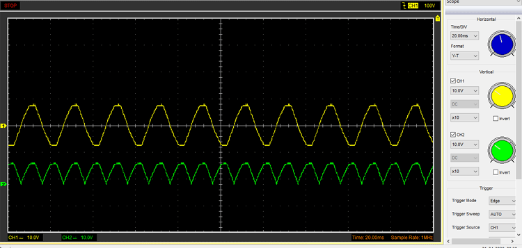
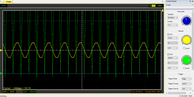
In my oscilloscope, the yellow signal is the input, and the green signal is the output. Instead of getting a half-wave rectification, we are getting a sort of full-wave rectification.
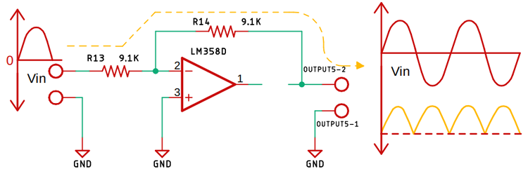
The above image shows you that when the diode is off, the negative half cycle of the signal flows through the resistor onto the output, and that is why we are getting the full-wave rectification, like the output, but this is not the actual case.
Let's see what happens when we connect a 1K load.
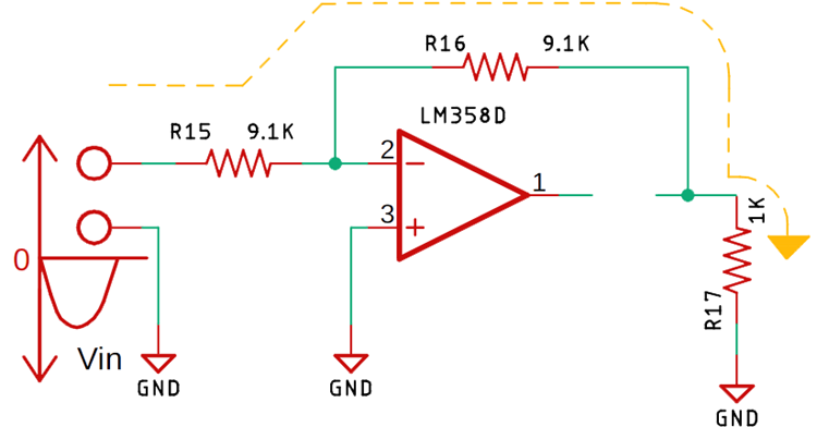
The circuit looks like the above image.

The output looks like the above image.
The output looks like this because we have practically formed a voltage divider circuit with two 9.1K and a 1K resistor, that is why the input positive half of the signal just got attenuated.

Again, the above image shows you what happens when I change the load resistor value to 220R from 1K.
This is not the least bit of a problem that this circuit has.
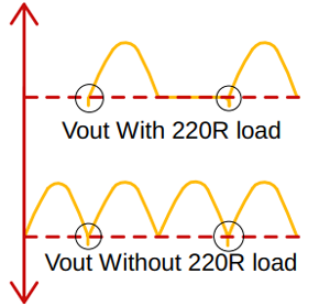
The above image shows you an undershoot condition where the output of the circuit goes below zero volts and rises after a certain spike.
The above image shows you an undershoot condition for both of the above-mentioned circuits, with and without load. That is because, whenever the input signal goes below zero, the op-amp goes into the negative saturation region and the result is the shown image.
Another reason we can say that, whenever the input voltage swings from positive to negative, it will take some time before the op-amp's feedback comes into play and stabilises the output, and this is why we are getting the spikes below zero volts on the output.
This is happening because I am using a jelly bean LM358 op-amp with a low slew rate. You can get away with this problem just by putting an op-amp with a higher slew rate. But keep in mind that this will also happen in the higher frequency range of the circuit.
The Modified Precision Rectifier Circuit
The above figure shows a modified precision rectifier circuit through which we can reduce all the above-mentioned flaws and drawbacks. Let's study the circuit and figure out how it works.
Improved Half-Wave Precision Rectifier Design
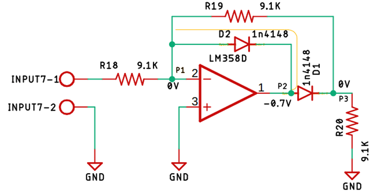
Now, in the above circuit, you can see that the diode D2 will conduct if the positive half of the sinusoidal signal is applied as an input. Now the above-shown path (with the yellow line) is completed and the Op-amp is acting as an inverting amplifier, if we look at point P1, the voltage is 0V as a virtual ground is formed at that point, so current cannot flow through the resistor R19, and in the output point P2, the voltage is negative 0.7V as the op-amp is compensating for the diode drop, so there is no way that current can go to point P3. So, that is how we have achieved a 0V output whenever a positive half cycle of the signal is applied to the input of the Op-amp.
Now, let us assume that we have applied the negative half of the sinusoidal AC signal to the input of the op-amp. That means the applied input signal is less than 0V.
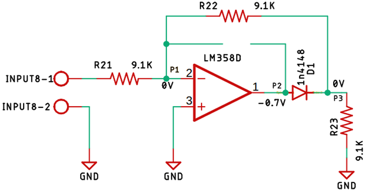
At this point, the Diode D2 is in the reverse-bias condition, which means it's an open circuit. The image above exactly tells you that.
As the Diode D2 is in the reverse-bias condition, the current will flow through the resistor R22, forming a virtual ground at point P1. Now, when the negative half of the input signal is applied, we will get a positive signal in the output as it's an inverting amplifier. And the diode will conduct, and we will get the compensated output at point P3.
Now the output voltage will be -Vin/R2 = Vout/ R1
So the output voltage becomes Vout = -R2/R1* Vin
Now, let us observe the output of the circuit in the oscilloscope.

The practical output of the circuit without any load attached is shown in the above image.
Now, when it comes to the analysis of the circuit, a half-wave rectifier circuit is good enough, but when it comes to a practical circuit, the half-wave rectifier just does not make practical sense.
For that reason, a precision full wave rectifier was introduced. To achieve a precision full wave rectifier using op-amp, I just need to make a summing amplifier, and that's it.
Precision Full Wave Rectifier using Op-Amp
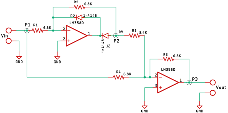
To make a full-wave precision rectifier circuit, I have just added a summing amplifier to the output of the previously mentioned half-wave rectifier circuit. From point P1 to point P2 is the basic precision rectifier circuit, and the diode is so configured that we get a negative voltage at the output.
Full Wave Precision Rectifier Circuit Analysis
From point P2 to point P3 is the summing amplifier; the output from the precision rectifier is fed to the summing amplifier through the resistor R3. The value of the resistor R3 is half of R5, or you can say it’s R5/2, which is how we are setting a 2X gain out of the op-amp.
The input from the point P1 is also fed to the summing amplifier with the help of the resistor R4; the resistors R4 and R5 are responsible for setting the gain of the op-amp to 1X.
Since the output from the Point P2 is fed directly to the summing amplifier with a gain of 2X, that means the output voltage will be 2 times the input voltage. Let's assume the input voltage is 2V peak, so we will get a 4V peak at the output. At the same time, we are directly feeding the input to the summing amplifier with a gain of 1X.
Now, when the summing operation happens, we get a summed up voltage at the output, which is (-4V) + (+2V) = -2V, and as the op-amp is at the output. As the op-amp is configured as an inverting amplifier, we will get +2V at the output, which is the point P3.
The same thing happens when the negative peak of the input signal is applied to the full wave precision rectifier using op amp.

The above image shows the final output of the circuit. The waveform in blue is the Input, and the waveform in Yellow is the output from the half-wave rectifier circuit, and the waveform in green is the output of the full wave precision rectifier using op amp.
Components Required for Full Wave Precision Rectifier
- LM358 op-amp IC - 2
- 6.8K, 1% Resistor - 8
- 1K Resistor - 2
- 1N4148 Diode - 4
- Bread Board - 1
- Jumper Wires - 10
- Power Supply (± 10V) - 1
Circuit Diagrams and Schematic
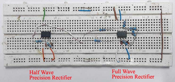
A circuit diagram for a half-wave and full-wave precision rectifier using an op-amp is given below:


For this demonstration, the circuit is constructed in a solderless breadboard, with the help of the schematic. To reduce parasitic inductance and capacitance, I have connected the components as close as possible.
Performance Enhancement and Troubleshooting
The circuit can be further modified to improve its performance, like we can add a filter in order to reject high-frequency noises.
This circuit is made just for demonstration purposes only. If you are thinking about using this circuit in a practical application, you have to use a chopper-type op-amp and high high-precision 0.1-ohm resistor to achieve absolute stability.
Precision Rectifier Circuit Troubleshooting Guide
| Problem | Possible Cause | Solution | Prevention |
|---|---|---|---|
| The output shows negative spikes | Low slew rate op-amp, saturation recovery | Use a higher slew rate op-amp (TL072, LF356) | Choose an op-amp with slew rate >1V/μs |
| Reduced output amplitude | Voltage divider effect with load | Use a buffer amplifier or reduce the load resistance | Design for specific load impedance |
| Distorted waveform | Insufficient power supply voltage | Increase supply voltage to ±12V or ±15V | Ensure supply voltage > peak input + 3V |
| No rectification | Diode connected in reverse | Check the diode polarity and reconnect correctly | Mark the diode orientation during assembly |
I hope you liked this article and learned something new from it. If you have any doubts, you can ask in the comments below or use our forum for detailed discussion.
Frequently Asked Questions
⇥ What is a precision rectifier circuit using an op-amp?
An op-amp precision rectifier circuit is an electronic circuit that converts AC signals to DC voltage with an operational amplifier. The op-amp precision rectifier circuit is used to eliminate the common 0.7V voltage drop for a diode, allowing rectification of low-amplitude signals that are not handled well by a regular diode rectifier circuit.
⇥ How does a half-wave precision rectifier work?
The half-wave precision rectifier circuit works with an op-amp in the feedback loop with a diode. During the positive input cycles, the op-amp will drive the diode to conduct, compensating for the diode drop. During the negative input cycles, the diode blocks the current, and the output will be equal to zero. The op-amp provides feedback that allows the output to exactly follow the positive input through the diode without losing any voltage.
⇥ What are the benefits of a precision full-wave rectifier using an op-amp?
A precision full-wave rectifier that utilizes an op-amp offers the following benefits: (1) 100% efficiency by rectifying both half cycles, (2) No concern of compensating for the voltage drop of diodes, (3) capability of using very small input signals, (4) output voltage will match the input voltage across the full amplitude of the input, and (5) improved ripple factor over conventional rectifiers.
⇥ When would you use a precision rectifier instead of a normal diode rectifier?
Precision rectifiers will be used instead of normal diode rectifiers for the following reasons: (1) to avoid the 0.7V limitation associated with regular diodes, (2) they can rectify signals below 0.7V, (3) they give an exact voltage relationship of the input to the output voltage, (4) they are more precise in measurement applications, and (5) they make it possible to rectify millivolt level signals in instrumentation applications.
More Op-Amp Projects to Expand Your Analog Circuit Skills
Dive into the world of op-amp-based designs with these hands-on circuits that explore timing, waveform generation, and controlled current sources.

Astable Multivibrator Circuit Using an Op-amp
In this project, we are going to build a simple Astable Multivibrator using an Op-amp, and we will look at all the necessary calculations to find out the period, hence we can calculate the frequency and duty cycle of the circuit.

Monostable Multivibrator Circuit using Op-amp
In this tutorial, we will be making an op-amp-based monostable multivibrator circuit along with all its calculations, and testing.

Design a Voltage Controlled Current Source Circuit using an Op-Amp
In this project, we will explain how a voltage-controlled current source using an op-amp can be designed and also build it to demonstrate its working.
Comments
Yes you are right. it's a mistake from my side i will fix this as soon as possible. Thanks.
Hi.....can i use the above circuit to convert 0-24VAC to 0-24VDC from Current Transformer? Thank you.
I don't know why, but this circuit doesn't work for me. I am trying to convert 600mv AC signal to DC without any voltage drop. But when I try this with full wave precision rectifier, there is a huge drop of voltage in the output. I just only can get an output of 32mv DC for 400mv AC. Please help me in getting rid of this. For the past 2 week i,m stuck in this circuit, i need it for my project.

Well explained Debashis, but look at the part where you mention
"Now the output voltage will be -Vin/R2 = Vout/ R1
So the output voltage becomes Vout = -R2/R1* Vin".
There are no such resistors! For someone familiar with how op-amps work, this is not difficult to figure out, but your description needs to be consistent with component names used.
Good job, but you need to proof read your articles.
Cheers.