
Operational Amplifiers (Opamp) has so many interesting applications, and we have already created many circuits using op-amps. Today we are going to study one more application of Opamp which is to add two or more input voltages and the circuit is called Summing amplifier or Opamp Adder. Here we will use LM358 Opamp to demonstrate the Adder Circuit.
Required Components:
- LM358 Dual-Operational Amplifiers
- Resistor 1KΩ -4Nos
- Power supply (for opamp +Vcc & -Vcc) 9 Vdc
- Two Input voltage sources (their sum should be < supply voltage)
- Digital Multi-meter DMM for testing
Before going into detail we will first learn about operational amplifiers and LM385.
Op-amp (Operational Amplifier):
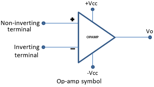
Op-amp basically has Voltage Comparator inside, which has two inputs, one is inverting input and second is non-inverting input. When voltage at non-inverting input (+) is higher than the voltage at inverting input (-), then the output of comparator is High. And if the voltage of inverting input (-) is Higher than non-inverting end (+), then output is LOW. Op-amps have large gain and usually used as Voltage Amplifier. Some Op-amps have more than one comparator inside like op-amp LM358 has two, LM324 has four LM741 has only one comparator.
OpAmp are used in AC as well as DC amplification. Opamp is used in various applications like amplification, filtering, signal conditioning, adding or subtracting the voltage etc.
Opamp symbol is as shown below-
Ideal characteristics of OP-AMP:
- Rin = ∞ It means it does not allows current to flow into the input terminals.
- Ro = 0 It allows current to flows from output terminals
- Open Loop Gain, (Avo) = ∞
- Bandwidth, (BW)= ∞
- Offset Voltage, (VIO)
Although above are the ideal characteristics of Opamp, it does not behave this way. It allows some input current and does not have infinite gain.
Op-amp LM358:
LM358 is a Dual Low Noise Operational Amplifier which has two independent voltage comparators inside. This is a general purpose op amp which can be configured in many modes like comparator, summer, integrator, amplifier, differentiator, inverting mode, non- inverting mode, etc.

To learn more about LM358 go through LM358 various circuits as amplifier and comparator.
Inverting Operational Amplifier Configuration
Here we are building Adder circuit using Inverting Amplifier. So in order to understand the Summing circuit of Inverting Opamp, we have to look first at how an inverting opamp works in closed loop configuration. The closed loop circuitry of inverting opamp is very useful and has two most important characteristics, which makes an opamp to use in various application and they are as follows:-
In closed loop configuration,
- No Current Flows into the Input Terminals
- The Differential Input Voltage is Zero as V1 = V2 = 0 (Virtual Earth), OR the opamp tries to keep both the inputs at same level or same value even if it’s one of terminal is not grounded.
Below is a closed loop inverting OpAmp circuit that is negative feedback is given from output to the input. And because of this negative feedback, voltage at inverting input becomes equal to the voltage at non-inverting input, hence creating a virtual ground.
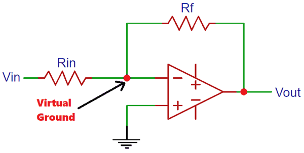
We know from the Inverting Op-amp Gain formulae,
Gain (Av) = Vout / Vin = (Rf / Rin)
Inverting Adder Circuit / Summing Amplifier Working:
Inverting adder circuit is similar to the above inverting amplifier in which the input voltages are given to the inverting terminal and non-inverting terminal is grounded, but the difference in Inverting adder circuit is it has multiple inputs at its inverting terminal. Below is the circuit of Inverting Adder Circuit with two inputs at the inverting input.
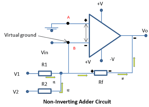
In the circuit the non-inverting terminal is grounded, and as seen in closed loop configuration, voltage at point B will be same as voltage at point A, 0V. Therefore the current I1 and I2 will flow into the resistor Rf (the higher potential) and not into the inverting terminal (the lower potential) of op-amp. The output voltage obtain will be the sum of the inputs and will be negative in nature since input are applied to the non-inverting terminal.
Here is the practical implementation of Opamp adder circuit using LM358.We have used two separate batteries (≈4 Vdc and ≈2.6 Vdc) for two input voltages and you can see the sum of two input voltages (6.89v) in Multimeter in below picture.

Inverting Op-amp Adder Circuit Analysis:
The gain equation for inverting amplifier is,
Vout = (Rf/R) Vin
Applying KCL to the circuit,
I1 + I2 = If
(V1-0/R1) + (V2-0/R2) = (0-Vo/Rf)
(V1/R1) + (V2/R2) = -Vo/Rf
Vo= - Rf * { (V1/R1) + (V2/R2) }  ……… Equation-1
Vo= - { (RfV1/R1) + (RfV2/R2) },
If there are n inputs then
Vo= - Rf * { (V1/R1) + (V2/R2) +………..+(V2/Rn) }
Let’s us consider R1=R2=Rf=R
Vo= - (V1+ V2); when R1=R2=Rf=R
Vo= - (V1+ V2……+Vn); (for n number of inputs)
This is called unity gain inverting adder
And if R1=R2=R≠Rf then
Vo= - (Rf/R) (V1 + V2);
Vo= - (Rf/R) (V1+ V2……+Vn); (for n number of inputs)
So in op-amp adder output voltage is proportional to the sum of input voltages.
So this is how an inverting Op-amp in closed-loop configuration with multiple inputs can be used as Adder or Summing amplifier circuit. Likewise we can build the Op-amp adder with non-inverting op-amps.
