

The multivibrator circuit is very popular and useful in the field of electronics, and it’s the most basic circuit that you will know about while learning basic electronics. The multivibrator circuit can be divided into two categories: the first one is known as the monostable multivibrator, and the second one is known as the astable multivibrator. But in this project, we will talk about the astable multivibrator, sometimes also known as a free-running multivibrator.
By definition, an Astable multivibrator circuit is a circuit that has no stable state. It means once powered on, it starts and it continues to oscillate between high and low states until the power is off. When it comes to making such an Astable multivibrator, the most common way is to use a 555 Timer IC. In one of our previous projects, we made an Astable Multivibrator Circuit Using the 555 Timer IC. You can check that out if you are looking for something like that. But in a production environment, while there is complex circuitry involved, putting more ICs just adds up to the BOM cost. A simpler solution could be to use an Op-amp to generate an Astable signal. This circuit can be used in a variety of applications where a simple square wave signal is a requirement.
So, in this project, we are going to build a simple Astable Multivibrator using Op-amp, and we will look at all the necessary calculations to find out the period, hence we can calculate the frequency and duty cycle of the circuit. We have also covered basic op-amp circuits like the Summing Amplifier, Differential Amplifier, Instrumentation Amplifier, Voltage Follower, Op-Amp Integrator, etc.
Table of Contents
- What is an Astable Multivibrator Using Op-Amp?
- Key Features of Op-Amp Astable Multivibrator
- How does this Astable Multivibrator with Op-amp Work?
- The Calculation For The Astable Multivibrator Using Op Amp Formula
- Components Required to Build Op-amp Based Astable Multivibrator Circuit
- Astable Multivibrator Using Op Amp Circuit Diagram- Schematic
- Free Running Multivibrator Working Principle
- Frequently Asked Questions
- Other Op-Amp Circuits
What is an Astable Multivibrator Using Op-Amp?
An astable multivibrator using op-amp is a free-running oscillator circuit that continuously alternates between two states (or outputs) without any external trigger. Unlike the traditional 555 timer, which requires an external clock trigger to change the circuit state each cycle, astable multivibrators using op-amps do not come with the same limitations. This makes them ideal for applications requiring low-cost, high-speed manufacturing and provides better frequency stability than traditional 555 circuits in complex designs
Key Features of Op-Amp Astable Multivibrator
Feature | Description |
|---|---|
No Stable State | Switches back and forth from high to low, but never settles. |
Self-Sustaining | Once powered, needs no external trigger to actuate. |
Square Wave Output | Delivers a tidy, square wave-like digital instantaneous feedback at its output. |
Adjustable Frequency | Frequency of oscillation is determined by resistor-capacitor components. |
Low Component Count | A minimum of components are used making it an uncomplicated and cost effective build. |
How does this Astable Multivibrator with Op-amp Work?
The answer to this question is very simple, but to understand this, you need to first understand a circuit, which is known as the Schmitt trigger circuit. A simplified circuit of the Schmitt trigger is shown below.
The Schmitt Trigger Circuit:
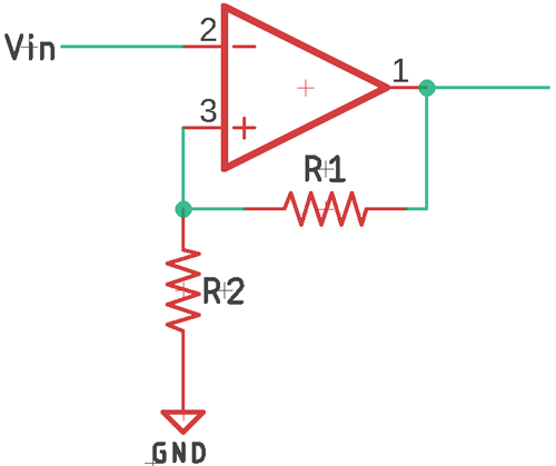
The above schematic shows an Op-amp circuit with positive feedback. When an Op-amp is configured with positive feedback, it’s commonly known as the Schmitt trigger. But for the sake of simplicity, let’s understand the Schmitt trigger circuit.
This circuit uses a voltage divider to use a device in the output voltage and feeds that to the non-inverting terminal. But because of the positive feedback, the output will continuously grow until it reaches saturation.
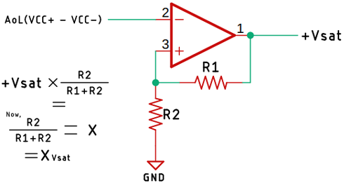
Now, let’s consider that the output voltage of the Schmitt trigger is equal to the positive saturation voltage defined as +Vsat, and the fraction of this voltage is given to the non-inverting terminal.
Which is +Vsat x (R2/(R1+R2)). Now, if we consider this equation as X, the final equation becomes Xvsat. Where X is the feedback voltage, we get from the voltage divider. Now, when the input voltage Vin is less than the voltage at Xvsat, then the output will be at positive saturation voltage. Because the output of the op-amp can be given as open-loop gain multiplied by the difference of two-terminal voltage. Which is AoL(VCC+ - VCC-). Now, when the voltage at the inverting terminal is greater than Xvsat, the output will saturate at the negative saturation voltage. If you put the numbers in the above equation, you can find that out.
For better understanding, if we look at the transfer function of the Schmitt trigger circuit, it will look like the image shown below.
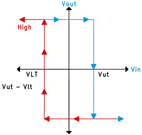
Here, the upper threshold voltage is represented as VUT, and the lower threshold voltage is represented as VLT. As you can see, when the input voltage is greater than the upper threshold voltage, the output will switch from positive saturation voltage to negative saturation voltage. Whenever the input is less than the lower threshold voltage, the output will switch from negative saturation voltage to positive saturation voltage. This is the basic working of the Schmitt trigger circuit.
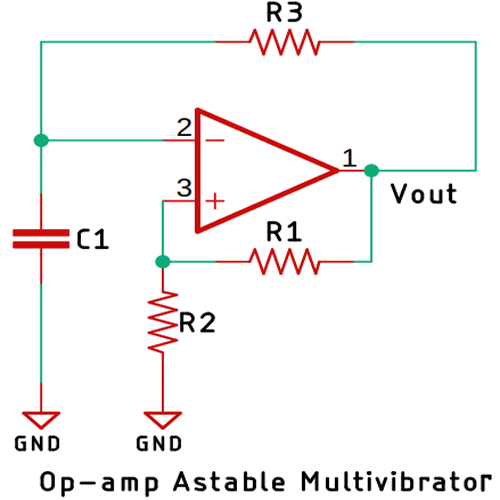
In all the above scenarios, we have provided all the signals externally. If we provide feedback to the input with the help of a capacitor and a resistor, then we can use the Schmitt trigger circuit as an Astable multivibrator. You can see the schematic of this Op-amp Astable multivibrator circuit below.
Working of the Astable Multivibrator using Op-amp:
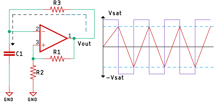
Now, we will assume that the output of the circuit is in positive saturation voltage also, because we have put a resistor R3 as feedback, the current will start flowing through the resistor R3, and the capacitor will start charging slowly. As you can see in the above image, it is shown with the black dotted line. When the capacitor charges reach the upper threshold voltage, the output will switch from positive saturation voltage to negative saturation voltage. When that happens, the capacitor will start discharging towards the negative saturation voltage. Now, when the voltage at the non-inverting terminal is slightly more than the inverting terminal, the output will again switch from negative saturation voltage to positive saturation voltage. This way, by the charging and discharging process, this circuit can generate the Astable signal at the output.
In this circuit, the time-period is dependent upon the value of the resistor and the capacitor. It also depends upon the upper and lower threshold voltage of the op-amp. This is how an Op-amp based Astable multivibrator circuit works. Now that we have understood the basics, we can move on to the calculation of the circuit. You can also check out our article on the Free Running Frequency of Astable Multivibrator to know more.
The Calculation For The Astable Multivibrator Using Op Amp Formula
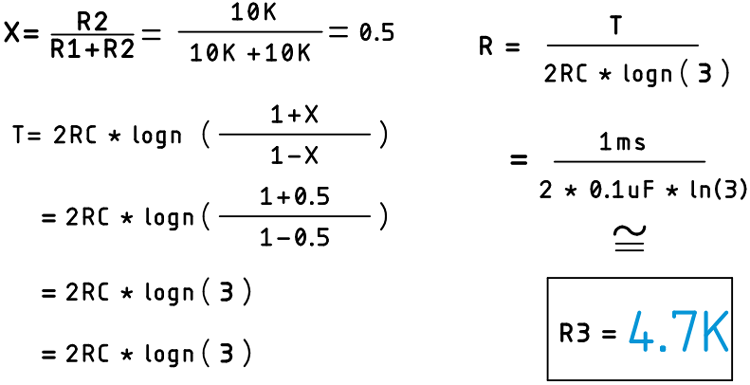
The time period, or simply say the output frequency, is determined by the value of the resistor R3, the capacitor C1, and the value of the feedback resistor ratio. For simplicity, we are calculating the value of the resistor and capacitor with a 50% duty cycle. If the upper and the lower voltages are different, then the duty cycle can be more or less than 50%. We will assume the output frequency of the circuit is 1KHz. As the frequency is 1KHz, the time period T will be 1ms, which we can easily find out from the formula T=1/F.
To calculate the time period, the formula shown below can be used.
T = 2RC * logn ((1+X) / (1-X))
Where R is the Resistance, C is the capacitance, and we have to use the Natural Logarithmic function to calculate the value. The reason why we have to use the natural logarithmic function is out of the scope of this article, because for that we have to prove the formula shown above.
Now, we will consider the values for R1 = R2 = 10K, C = 0.1uF, and we will find out the value for R3. We know that F = 1KHz.
Once the calculations are done, we have all the values, and now we can move on to making the actual circuit and testing it with the oscilloscope.
Components Required to Build Op-amp Based Astable Multivibrator Circuit
As this is a simple Astable multivibrator, the component requirements for this project are very simple, and you can get those from your local hobby store. The list of components is given below.
- LM358 Op-amp IC - 1
- 10K Resistors - 2
- 4.7K Resistor - 1
- 0.1uF Capacitor - 2
- 1N4007 Diode - 4
- 1000uF, 25V Capacitors - 2
- 4.5V - 0 - 4.5V Transformer - 1
- AC Cable - 1
- Breadboard - 1
- Connecting Wires
Astable Multivibrator Using Op Amp Circuit Diagram- Schematic
The circuit diagram for the Op-amp based Astable Multivibrator Circuit is given below.

Free Running Multivibrator Working Principle
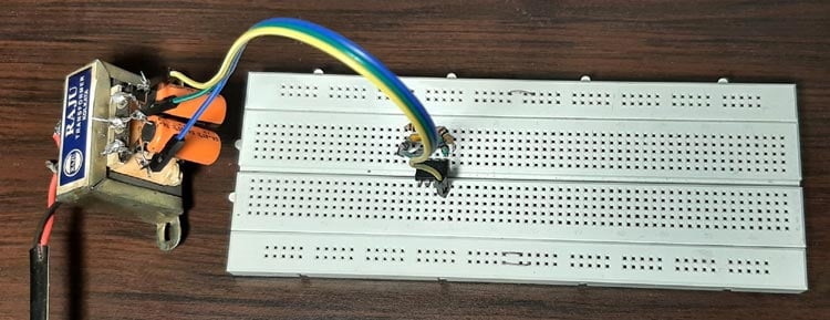
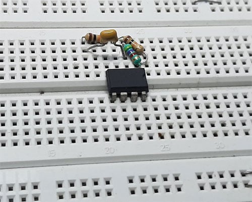
The test setup for the Op-amp based multivibrator circuit is shown above. As you can see, we have used a transformer with four diodes and two capacitors to produce a dual polarity supply, and we have used two 10K resistors, one 4.7K resistor, and a 0.1uF capacitor to build the circuit around the LM358 Op-amp. A clear image of the circuit is shown below.
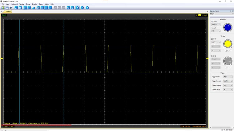
After the circuit was complete, I pulled out my Hantek oscilloscope to measure the frequency, and it was around 920Hz. It was a little off, but that’s due to the value of the resistor and capacitor. With that, we conclude the project. A snapshot of the output is shown below.
Frequently Asked Questions
⇥ How does an op-amp configured as a free-running multivibrator work?
A free-running multivibrator is an op-amp set up as a Schmitt trigger with positive feedback, a timing RC network, and charging and discharging the capacitor between the upper and lower thresholds. This makes the output automatically switch between +Vsat and -Vsat, thus creating a continuous oscillator without an external input.
⇥ What are the differences between a 555 timer and an op-amp astable multivibrator?
An op-amp astable multivibrator is less expensive (fewer components), has more reliable frequency stability, a more flexible design, a wider frequency range, and is easier to calculate. The 555 timer guarantees usable functionality, consistent timing, has current output capabilities, and is simpler for novices.
⇥ What are the uses of the op-amp astable multivibrator?
Common uses include: Clock signal generation for digital circuits, pulse width modulation signal generation for motor control, LED flasher circuits, frequency reference for phase locked loops (PLLs), test signal generation, control of switching power supplies, audio tone generation, and timing circuits on embedded systems.
⇥ Why doesn't my op-amp astable multivibrator oscillate?
Here are common things to check:
1) Power supply -make sure the supply voltage is ±5V minimum
2) Positive feedback - check the feedback loop through the feedback resistor from the output to the positive input.
3) Damage - make sure the op-amp you are using is serviceable
4) Component values and connections - cosmetics matter! Make sure all prototyping connections and components have the correct values.
5) Capacitor - make sure your timing capacitor isn't shorted/open in the PCB or breadboard circuit.
6) Timing resistor value - make sure your timing resistor is in the range between 1kΩ and 1MΩ.
I hope you liked the article and learned something new. If you have any questions regarding the article, you can ask in our Electronics forum.
Other Op-Amp Circuits
Explore other foundational op-amp configurations that play key roles in signal processing and circuit design.

Summing Amplifier or Op Amp Adder Circuit
We are going to study one more application of Opamp which is to add two or more input voltages and the circuit is called Summing amplifier or Opamp Adder.

Differential Amplifier or Voltage Subtractor Circuit
We will learn how to use an op-amp as a Differential amplifier to find the voltage difference between two voltage values. It is also called the Voltage Subtractor.

Instrumentation Amplifier Circuit using Op-Amp
An Instrumentation amplifier a.k.a INO or in-amps as the name suggests amplifies the variation in voltage and provides a differential output like any other op-amps.
