

Almost all types of sensors and transducers convert real world parameters like light, temperature, weight etc into voltage values for our electronic systems to understand it. The variation in this voltage level will help us in analyzing/measuring the real world parameters, but in some applications like biomedical sensors this variation is very small (low-level signals) and it is very important to keep track of even the minute variation to get reliable data. In these applications an Instrumentation Amplifier is used.
An Instrumentation amplifier a.k.a INO or in-amps as the name suggests amplifies the variation in voltage and provides a differential output like any other op-amps. But unlike a normal amplifier the Instrumentation amplifiers will have high input impedance with good gain while providing common mode noise rejection with fully differential inputs. It’s okay if you don’t get it now, in this article we will learn about these Instrumentation amplifiers and since these IC’s are relatively expensive than Op-amps we will also learn how to use normal Op-amp like LM385 or LM324 to build an Instrumentation amplifier and use it for our applications. Op-amps can also be used to build Voltage adder and voltage Subtractor circuit.
What is an Instrumentation Amplifier IC?
Apart from normal op-amps IC we have some special type of amplifiers for Instrumentation amplifier like INA114 IC. It is nothing more than few normal op-amps combined together for certain specific applications. To understand more about this lets look into the datasheet of the INA114 for its internal circuit diagram.
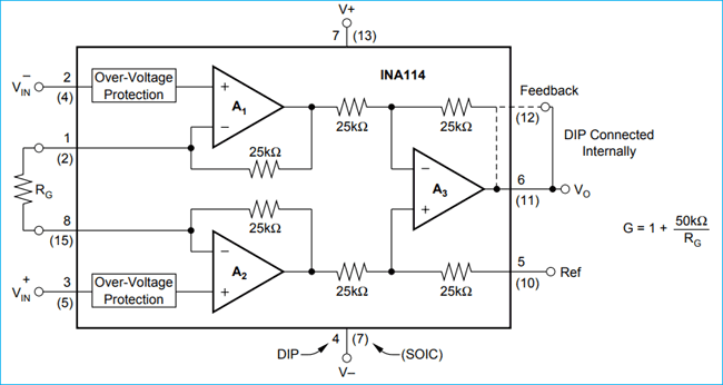
As you can see the IC takes in two signal voltages VIN- and VIN+, let’s consider them as V1 and V2 from now for ease of understanding. The output voltage (VO) can be calculated using the formulae
VO = G (V2 – V1)
Where, G is the gain of the op-amp and can be set using the external resistor RG and calculated using the below formulae
G = 1+ (50kΩ/RG)
Note: The value 50k ohm is applicable only for the INA114 IC since it uses resistors of 25k (25+25 =50). You can calculate the value for other circuits respectively.
So basically now if you look at it, an In-amp just provides the difference between two voltage sources with a gain that can be set by an external resistor. Does this sound familiar? If not take a look at the Differential amplifier design and come back.
Yes!, this is exactly what a Differential amplifier does and if you take a closer look you can even find that the op-amp A3 in the above image is nothing but a Differential amplifier circuit. So in layman terms, an Instrumentation-amp is yet another kind of differential amplifier but with more advantages like high input impedance and easy gain control etc. These advantages are because of the other two op-amp (A2 and A1) in the design, we will learn more about it in the next heading.
Understanding the Instrumentation Amplifier
To completely understand the Instrumentation amplifier, let’s break it down the above image into meaningful blocks as shown below.
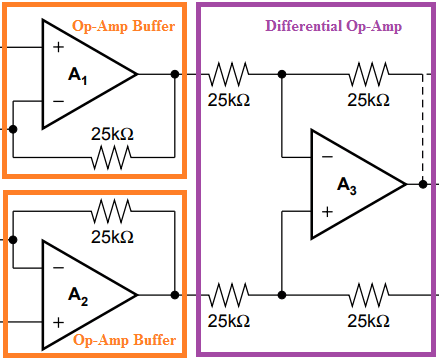
As you can see the In-Amp is just a combination of two Buffer op-amp circuit and one differential op-amp circuit. We have learnt about both these op-amp design individually, now we will see how they are combined to form a differential Op-amp.
Difference between Differential Amplifier and Instrumentation Amplifier
We have already learnt how to design and use a differential amplifier in our previous article. Few considerable disadvantage of differential amplifier is that it has very low input impedance because of the input resistors and has very low CMRR because of the high common mode gain. These will be overcome in a Instrumentation amplifier because of the buffer circuit.
Also in a differential amplifier we need to change a lot of resistors to change the gain value of the amplifier but in a differential amplifier we can control the gain by simply adjusting one resistor value.
Instrumentation Amplifier Circuit Diagram using Op-amp (LM358)
Now let’s build a practical Instrumentation amplifier using op-amp and check how it is working. The op-amp instrumentation amplifier circuit that I am using is given below.

The circuit requires three op-amps all together; I have used two LM358 ICs. The LM358 is a dual package op-amp that is it has two op-amps in one package so we need two of them for our circuit. Similarly you can also use three single-package LM741 op-amp or one quad package LM324 op-amp.
In the above circuit, the op-amp U1:A and U1:B acts as a voltage buffer this helps in achieving high input impedance. The op-amp U2:A acts as a differential op-amp. Since all the resistors of differential op-amp is 10k it acts as a unity gain differential amplifier meaning the output voltage will be the difference of voltage between pin 3 and pin 2 of U2:A.
The output voltage of the Instrumentation amplifier circuit can be calculated using the below formulae.
Vout = (V2-V1)(1+(2R/Rg))
Where, R = Resistor value the circuit. Here R = R2=R3=R4=R5=R6=R7 which is 10k
Rg = Gain Resistor. Here Rg = R1which is 22k.
So the value of R and Rg decides the gain of the amplifier. The value of gain can be calculated by
Gain = (1+(2R/Rg))
Simulation of Instrumentation Amplifier Circuit
The above circuit when simulated gives the following results.
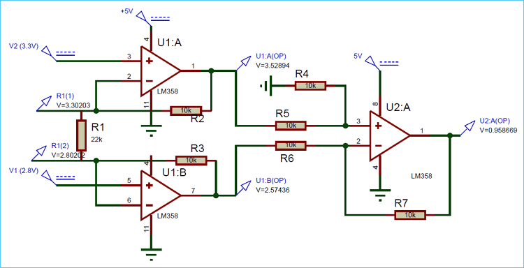
As you can see the input voltages V1 is 2.8V and V2 is 3.3V. The value of R is 10k and the value of Rg is 22k. Putting all these values in the above formulae
Vout = (V2-V1)(1+(2R/Rg))
= (3.3-2.8)(1+(2x10/22))
= (0.5)*(1.9)
= 0.95V
We get the value of output voltage to be 0.95V which matches with the simulation above. So the gain of the above circuit is 1.9 and the voltage difference is 0.5V. So this circuit will basically measure the difference between the input voltages and multiply it with the gain and produce it as the output voltage.
You can also notice that the input voltage V1 and V2 appears across the resistor Rg this is due to the negative feedback of the Op-amp U1:A and U1:B. This ensures that the voltage drop across Rg is equal to the voltage difference between V1 and V2 which causes equal amount of current to flow through resistors R5 and R6 making the voltage on pin 3 and pin 2 equal on op-amp U2:A. If you measure the voltage before resistors you can see actual output voltage from the op-amp U1:A and U1:B whose difference will be equal to the output voltage as shown above in the simulation.
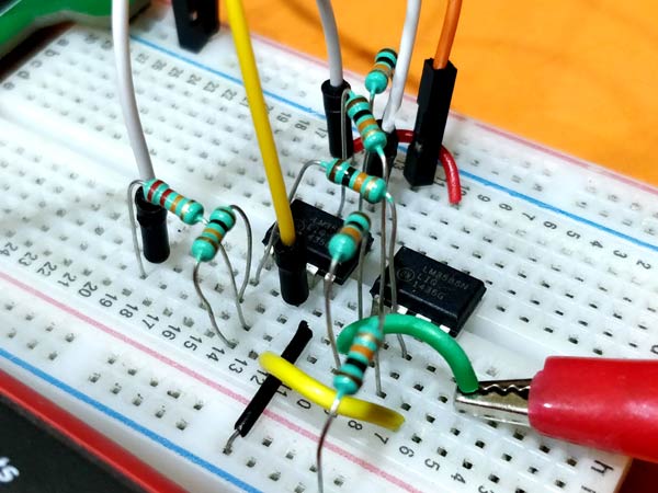
Testing the Instrumentation Amplifier Circuit on Hardware
Enough Theory lets actually build the same circuit on a breadboard and measure the voltage levels. My connection setup is shown below.
I have used the breadboard power supply that we built earlier. This board could deliver both 5V and 3.3V. I am using the 5V rail to power my both op-amps and the 3.3V as the signal input voltage V2. The other input voltage V2 is set to 2.8V using my RPS. Since I have also used 10k resistor for R and 22k resistor for R1 the gain of the circuit will be 1.9. The difference voltage is 0.5V and the gain is 1.9 product of which will give us 0.95V as output voltage which is measured and displayed in the image using a multimeter. The complete working of instrumentation amplifier circuit is show in the video linked below.
Similarly you can change the value of R1 to set the gain as required using the formulae discussed above. Since the gain of this amplifier can be controlled very easily using a single resistor it is often used in volume control for audio circuits.
Hope you understood the circuit and enjoyed learning something useful. If you have any questions leave them in the comment section below or use the forum for faster response.

Can I use this application for tiny input is 0,1mV ???