
Most of the Analog Electronic circuits require dual power supply rails for proper balanced operation; this gets especially critical if we are designing Operational amplifier circuits. Negative supply voltage is also required in digital systems like A/D converters, op amps and comparators. In all these cases, the current requirement will be low, but generating such a -5V supply is usually expensive and inefficient if we use a large number of discrete and integrated-circuit components. So in this tutorial we will learn how to build a simple low current dual 5V Power Supply Circuit that can be powered from our USB ports. Similarly we have previously built +12V and -12V Dual Power Supply Circuit.
Though there are many methods to split single voltage, their virtual ground potential will not be constant. If we use two batteries to obtain dual polarity voltage, in due course one battery will drain faster than the other and it gets difficult to maintain balanced dual polarity voltage. If you use resistor potential divider, some power is dissipated as heat and splitted voltage is not stable. To overcome these problems we will use a CMOS Voltage converter IC called ICL7660 from Renesas.
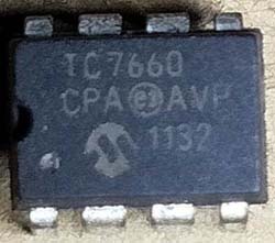
ICL7660
The ICL7660 and ICL7660A are monolithic CMOS charge pump voltage converters that converts the input voltage ranges of +1.5V to +10.0V to the output voltage ranges of -1.5V to -10.0V.
The ICL7660 and ICL7660A contain all the necessary circuitry to complete a negative voltage converter, except the two external capacitors. The working of the device can be best understood by the ideal voltage converter theory given below.
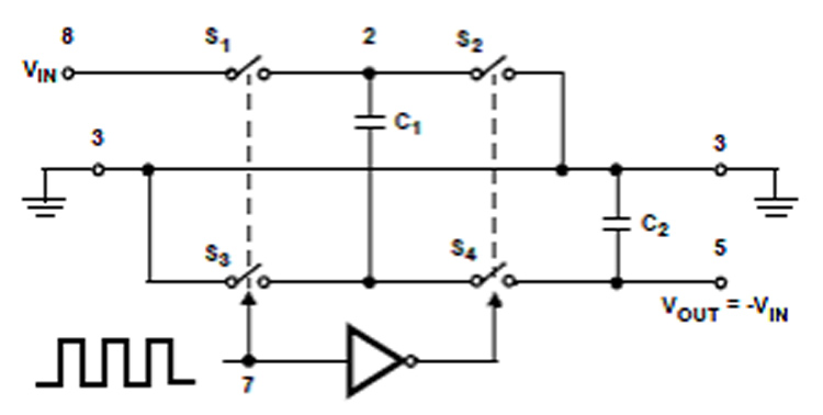
During the first half cycle, the switches S1 and S3 are closed (Note: Switches S2 and S4 are open during this half cycle). The Capacitor C1 is charged to a voltage V+. During the second half cycle of operation, switches S2 and S4 are closed (Note: Switches S1 and S3 are open during this half cycle). The voltage on the capacitor C1 shifts negatively by V+ volts. The Charge is then transferred from C1 to C2, assuming ideal switches and no load on C2. Thus the inverted V+ voltage is available across C2. The ICL7660 and ICL7660A operation is similar to this ideal operation of the voltage converter.
ICL7660 Application Tips:
- The capacitor C2 should be placed nearby to IC2 to prevent device latch up. Do not give more than 10V for ICL7660, 12V for ICL7660A.
- Do not connect LV terminal to GROUND for supply voltages greater than 3.5V.
- When using polarized capacitors, the '+' terminal of C1 must be connected to pin 2 of the ICL7660 and ICL7660A and the '+' terminal of C2 must be connected to GROUND.
- For best performance, use low value ESR capacitors in place of C1 and C2.
- A buffer capacitor can be connected across the input supply if the distance of the wire between the USB and the circuit is long.
- The output current of this circuit is limited to 40mA. For current requirement upto 100mA, the IC MAX660 can be used in place of U1.
5v Power Supply Circuit and Working:
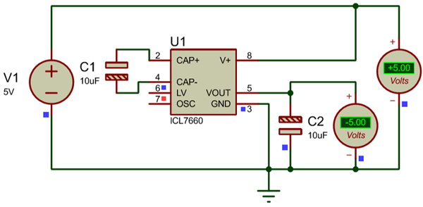
The complete ±5v power supply circuit diagram using ICL760 is shown below. The input voltage of +5V can be obtained from any USB port of laptop/computer or a charger/adapter.

The Circuit is built by around ICL7660 (U1) along with two capacitors (C1 and C2). The 5V output from USB is given to pin 8 of U1. The IC U1 and capacitors (C1 and C2) forms the voltage inverter section that converts +5V to -5V. The Converted -5V supply is available at pin 5 of U1. Thus the dual power 5V supply is available at the connector J2.
We have simulated the circuit in Proteus before building it on hardware:
Testing Dual (±) 5V USB Power Supply Circuit:
Assemble the circuit on the PCB/breadboard as per the circuit diagram shown above. Place the capacitor C2 as close to the IC U1. The IC should fixed with proper IC base if the circuit is soldered on PCB. Once the 5v power supply circuit is built it should look something like this
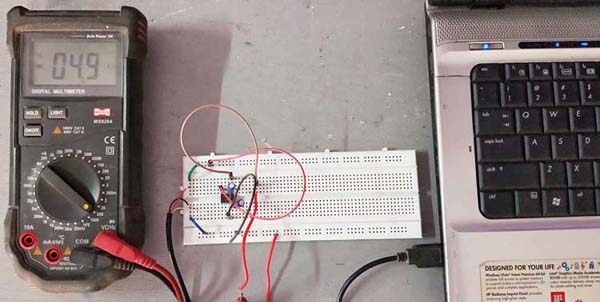
To test the circuit, connect the USB to laptop or power bank or any USB to power the circuit. Check the output voltage on J2 using multimeter with reference to ground. In the testing video given below, the multimeter is connected to the positive rail during when it shows 4.9V. Then the multimeter is connected to the output of the IC (i.e., pin 5 of ICL7660), then it shows -4.7V.
Below is the simulation
Hope you understood the circuit and learnt how to build a dual power supply circuit using the ICL7660 IC. If you have any questions leave them in the comment section or use our forums for more technical questions. Also check other power supply circuits, which includes various circuit like boost converter circuit, buck converter circuit, variable power supply circuit, SMPS circuit, Power bank circuit etc.

This was very useful for me. I'm thankful.