
If you are an RF Design Engineer or anyone who has worked with Wireless Radios, the term “Impedance Matching” should have struck you more than once. The term is crucial because it directly affects the transmission power and thus the range of our Radio modules. This article aims to help you understand what Impedance Matching is from the basics and will also help you to design your own impedance matching circuits by using an Impedance Matching Transformer, which is the most common method. So, let's dive in. Building a DIY impedance matching transformer requires careful consideration of core selection, winding techniques, and frequency characteristics.
Table of Contents
- What is an Impedance Matching Transformer?
- └ Specifications
- Standing Wave Ratio
- Core Principles
- └ Antenna Applications
- Formula & Calculations
- └ Understanding Transformer Ratio Impedance Relationships
- Transformer Matching Circuits - Example
- Autotransformer matching for Impedance balance
- └ Autotransformer Advantages
What is an Impedance Matching Transformer?
In short, Impedance matching makes sure that the output impedance of one stage, called the source, is equal to the input impedance of the following stage, called the load. This match allows for maximum power transfer and minimum loss. You can understand this concept easily by thinking about it as light bulbs in series with a power source. The first light bulb is the output impedance for stage one (a radio transmitter, for example), and the second light bulb is the load, or in other words, the input impedance of the second bulb (an antenna, for example). We want to make sure that the most power is delivered to the load; in our case, this would mean the most power is transmitted into the air so that a radio station can be heard from further away. This maximum power transfer occurs when the output impedance of the source is equal to the input impedance of the load, because if the output impedance is bigger than the load, more power is lost in the source (the first light bulb shines brighter).
Impedance Matching Transformer Specifications
If you are an RF design engineer or work with wireless radios, you are going to need to be familiar with impedance matching transformers, as they will help you maximise transmission power and distance with your radio module. This exhaustive guide on impedance matching transformers will describe impedance matching transformer working principles, some of the formulae you can use in practice, and the step-by-step method to make your own DIY impedance matching transformer specifically for antenna usage.
| Parameter | Description | Typical Values |
| Turns Ratio (n) | Primary to Secondary turns relationship | 1:1 to 1:10 |
| Impedance Ratio | Square of turns ratio | 1:1 to 1:100 |
| Frequency Range | Operating bandwidth | 1MHz - 30MHz |
| SWR Range | Standing Wave Ratio | 1:1 to 1.5:1 (optimal) |
Standing Wave Ratio – Measure of Impedance Matching
A measurement used to define how well two stages are matched is called SWR (Standing Wave Ratio). It is the ratio of the larger impedance compared to the smaller one; a 50 Ω transmitter into a 200 Ω antenna gives 4 SWR. A 75 Ω antenna feeding a NE612 mixer (input impedance is 1500 Ω) directly will have an SWR of 20. A perfect match, let’s say a 50 Ω antenna and a 50 Ω receiver, gives an SWR of 1. Impedance matching ensures that the output impedance of one circuit stage (source) equals the input impedance of the following stage (load).
In radio transmitters, SWRs below 1.5 are considered decent and operational, while SWRs above 3 can result in damage due to overheating of the power output stage devices (vacuum tubes or transistors). In receiving applications, high SWR won’t cause damage, but it will make the receiver less sensitive because the received signal will be attenuated due to the mismatch and consequent power loss.
Since most receivers use some form of an input bandpass filter, the input filter can be designed to match the antenna to the input stage of the receiver. All radio transmitters have output filters that are used to match the power output stage to the specific impedance (usually 50 Ω). Some transmitters have built-in antenna tuners that can be used to match the transmitter to the antenna if the antenna’s impedance is different from the specified transmitter’s output impedance. If there is no antenna tuner, an external matching circuit has to be used. The power loss due to a mismatch is hard to calculate, so special calculators or SWR loss tables are used. A typical SWR loss table is shown below
Understanding Impedance Matching: Core Principles
Using the SWR table above, we can calculate the power loss and also the voltage loss. Voltage is lost due to a mismatch when the load impedance is lower than the source impedance, and current is lost when the load impedance is higher than the source impedance.
Our 50 Ω transmitter with a 200 Ω antenna with 4 SWR will lose about 36% of its power, meaning that 36% less power will be delivered to the antenna compared to if the antenna had a 50 Ω impedance. The lost power will be mostly dissipated in the source, meaning if our transmitter was giving out 100W, 36W will be additionally dissipated in it as heat. If our 50 Ω transmitter were 60% efficient, it would dissipate 66 W when transmitting 100 W into a 50 Ω antenna. When connected to the 200 Ω antenna, it will dissipate an additional 36 W, so the total power lost as heat in the transmitter is 102 W. The increase of power dissipated in the transmitter not only means that full power is not being emitted by the antenna, but also risks damage to our transmitter because it dissipates 102 W instead of 66W, it was designed to work with.
Impedance Matching Transformer for Antenna Applications
In the case of a 75Ω antenna, feeding the 1500Ω input of the NE612 IC, we are not concerned with power being lost as heat, but about the increased signal level that can be achieved by the use of impedance matching. Let’s say that 13nW of RF is induced in the antenna. With a 75 Ω impedance, 13nW gives 1 mV - we want to match that to our 1500 Ω load. To calculate the output voltage after the matching circuit, we need to know the ratio of impedance, in our case, 1500 Ω/75 Ω=20. The voltage ratio (like turns ratio in transformers) is equal to the square root of the impedance ratio, so √20≈8.7. This means that the output voltage will be 8.7 times bigger, so it will be equal to 8.7 mV. The matching circuits act like transformers.
Since the power entering the matching circuit and the power leaving are the same (minus loss), the output current will be lower than the input one by a factor of 8.7, but the output voltage will be higher. If we matched a high impedance to a low one, we would get a lower voltage but a higher current.
Impedance Matching Transformer Formula & Calculations
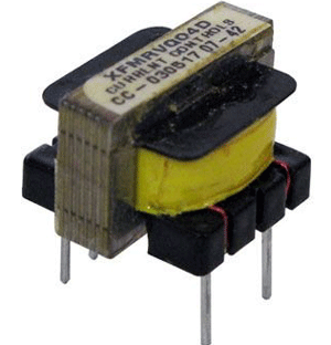
The impedance matching transformer working principle relies on the turns ratio relationship between primary and secondary windings. Special Transformers called Impedance Matching Transformers can be used to match impedance. The main advantage of transformers as impedance matching devices is that they have broadband, meaning they can work with a wide range of frequencies. Audio transformers using sheet steel cores, such as those used in vacuum tube amplifier circuits to match the high impedance of the tube to the low impedance of the speaker, have a bandwidth of 20Hz to 20kHz. RF transformers made using ferrite or even air cores can have bandwidths of 1MHz-30MHz. An impedance matching transformer is a specialised device that ensures maximum power transfer between circuits with different impedances.
Understanding Transformer Ratio Impedance Relationships
Transformers can be used as impedance matching devices because of their turns ratio, which changes the impedance that the source “sees”. You can also check the basics of the transformer article if you are completely new to transformers. If we have a transformer with a 1:4 turns ratio, this means that if 1V of AC is applied to the primary, we would have 4V of AC on the output. If we add a 4Ω resistor to the output, 1A of current will flow in the secondary, the current in the primary is equal to the secondary current multiplied by the turns ratio (divided if the transformer was of a step-down type, like mains transformers), so 1A*4=4A. If we use Ω’s law to determine the impedance that the transformer presents to the circuit, we have 1V/4A=0.25Ω, while we connected a 4Ω load after the matching transformer. The impedance ratio is 0.25Ω to 4Ω, or also 1:16. Understanding the impedance matching transformer formula is essential for designing effective matching circuits. It can also be calculated with this Impedance Ratio formula:
(nA/nB)²=ri
where nA is the number of primary turns on the winding with more turns, nB is the number of turns on the winding with fewer turns, and ri is the impedance ratio. This is how impedance matching happens. Let's work through a practical impedance matching transformer calculator example to demonstrate a real-world application:

If we used Ohm's law again, but now to calculate the power that flows into the primary, we would have 1V*4A=4W; in the secondary, we would have 4V*1A=4W. This means that our calculations are correct, that transformers and other impedance matching circuits don’t give more power than they are fed. No free energy here.
How to Select an Impedance Matching Transformer
A transformer matching circuit can be used when bandpass filtering is needed, and it should be resonant with the inductance of the secondary at the frequency of use. The main parameters of transformers as impedance matching devices are:
- Impedance ratio, or more commonly stated, turns ratio (n)
- Primary inductance
- Secondary inductance
- Primary impedance
- Secondary impedance
- Self-resonant frequency
- Minimum frequency of operation
- Maximum frequency of operation
- Winding configuration
- Presence of an air gap and max. DC
- Max. power
The primary turns number should be enough, so the primary winding of the transformer has reactance (it is a coil) four times the output impedance of the source at the lowest frequency of operation.
The secondary turns number is equal to the number of turns on the primary, divided by the square root of the impedance ratio.
We also need to know what core type and size to use; different cores work well in different frequencies, outside of which they exhibit loss.
Core size depends on the power flowing through the core, as each core exhibits losses, and bigger cores can dissipate these losses better and not exhibit magnetic saturation and other unwanted things as easily.
An air gap is required when a DC will flow through any winding on the transformer if the core used is made from steel laminations, like in a mains transformer.
Transformer Matching Circuits - Example
For example, we need a transformer to match a 50 Ω source to a 1500 Ω load in the frequency range of 3MHz to 30MHz in a receiver. We first need to know what core we would need since it is a receiver; very little power will flow through the transformer, so the core size can be small. A good core in this application would be the FT50-75. According to the manufacturer, its frequency range as a wideband transformer is 1MHz to 50MHz, good enough for this application.
Now we need to calculate the primary turns; we need the primary reactance to be 4 times higher than the source output impedance, so 200 Ω. At the minimum operating frequency of 3MHz, an inductor of 10.6uH has 200 Ω of reactance. Using an online calculator, we calculate that we need 2 turns of wire on the core to get 16uH, a bit above 10.6uH, but in this case, it is better for it to be bigger than to be smaller. 50 Ω to 1500 Ω gives an impedance ratio of 30. Since the turns ratio is the square root of the impedance ratio, we get around 5.5, so for each primary turn we need 5.5 secondary turns to make the 1500Ω at the secondary look like 50Ω to the source. Since we have 2 turns on the primary, we need 2*5.5 turns on the secondary, that is 11 turns. The diameter of the wire should follow the 3A/1mm2 rule (maximum of 3A flowing per each square millimetre of wire cross-section area).
Transformer matching is often used in bandpass filters to match resonant circuits to the low impedances of antennas and mixers. The higher the impedance loading the circuit, the lower the bandwidth and the higher Q. If we connected a resonant circuit directly to a low impedance, the bandwidth would often be too large to be useful. The resonant circuit consists of the secondary of L1 and the first 220 pF capacitor, and the primary of L2 and the second 220 pF capacitor. The transformer ratio impedance relationship is fundamental to all impedance matching applications. This relationship determines how effectively power transfers between different impedance levels.
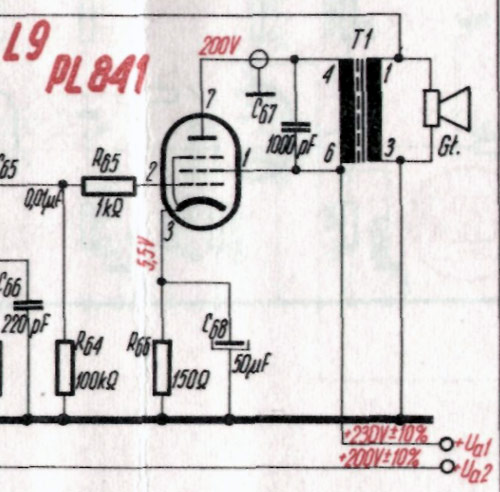
The above image shows a Transformer matching used in a vacuum tube audio power amplifier to match the 3000 Ω output impedance of the PL841 tube to a 4 Ω speaker. 1000 pF C67 prevents ringing at higher audio frequencies.
Autotransformer matching for Impedance balance
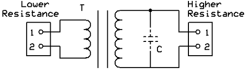
The autotransformer matching circuit is a variant of the transformer matching circuit, where the two windings are connected on top of each other. It is commonly used in IF filter inductors, together with transformer matching to the base, where it is used to match the lower impedance of the transistor to a high impedance that loads the tuning circuit less and allows for a smaller bandwidth and therefore greater selectivity. The process for designing them is practically the same, with the number of turns on the primary being equal to the number of turns from the tap of the coil to the “cold” or grounded end and the number of turns on the secondary being equal to the number of turns between the tap and the “hot” end or the end that is connected to the load.
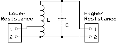
The above image shows an Autotransformer matching circuit. C is optional; if used, it should be resonant with the inductance of L at the frequency of use. This way, the circuit also provides filtering. Impedance matching transformers for antennas are critical for maximising radiated power and preventing transmitter damage.
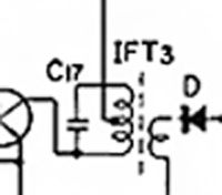
This image illustrates an Autotransformer and transformer matching used in an IF transformer. The autotransformer’s high impedance connects to C17; this capacitor forms a resonant circuit with the whole winding. Since this capacitor connects to the high impedance end of the autotransformer, the resistance loading the tuned circuit is higher; therefore, circuit Q is larger and IF bandwidth is reduced, improving selectivity and sensitivity. Transformer matching couples the amplified signal to the diode.
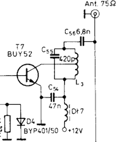
An autotransformer matching is used in a transistor power amplifier; it matches the 12 Ω output impedance of the transistor to the 75 Ω antenna. C55 is connected in parallel to the high impedance end of the autotransformer, forming a resonant circuit that filters out harmonics.
Autotransformer Advantages
» Reduced Component Count: Single winding design
» Better Coupling: Improved magnetic coupling efficiency
» Compact Size: Smaller physical footprint
» Lower Loss: Reduced winding resistance
Frequently Asked Questions on Transformer Ratio Impedance
⇥ 1. What is the basic operating principle of impedance matching transformers?
Impedance matching transformers use electromagnetic induction to change impedance levels from one circuit to another. Impedance transformation is based upon the turns ratio via the equation: Z₂/Z₁ = (N₂/N₁)² - and permits maximum power transfer from an impedance mismatch condition from one stage to another while abiding by the laws of conservation of power.
⇥ 2. What level of SWR indicates good impedance matching?
SWR < 1.5:1 indicates very good impedance matching, and there is very little power wasted. SWR = 1 is the ideal value for matching, and SWR > 3:1 can potentially damage the transmitter due to excessive reflected power, thus generating excessive heat in higher-powered applications.
⇥ 3. Are homemade impedance matching transformers available for the antenna application?
Yes, homemade impedance matching transformers are possible with ferrite cores (for example, FT50-75 ), suitable wire gauge, and suitable calculation of turn ratios. The need for success in this undertaking includes suitable ferrite core selection, winding accuracy, ample end-to-end testing with SWR analysers, and checking performance over the operating frequencies.
⇥ 4. What core material should I use for RF impedance matching transformers?
Ferrite cores with appropriate permeability should be used for RF applications (1-30MHz). FT50-75 cores will work for general-purpose applications, and there are various ferrite mixes to optimise performance at a range of frequencies. For higher frequencies, ferrite cores with lower permeability are preferable to reduce loss.
⇥ 5. How does an impedance mismatch hurt lossy transmitters?
An impedance mismatch means the power is reflected into the transmitter instead of being radiated from the antenna. The reflected power, in turn, becomes dissipated into heat within the output stage of the transmitter, thereby lowering its power efficiency. At higher power levels, it might even damage the transistor.
⇥ 6. How do I match a 75-ohm antenna to a 50-ohm transmitter?
Use an impedance match transformer having a turns ratio of 1 to 1.22 (√(75/50)). This is an acceptable SWR of 1.5:1, and losses are only 4% of the power. Secondly, for special frequency applications, use a quarter-wavelength matching section with 61.2-ohm characteristic impedance.
⇥ 7. What is transformer impedance matching versus autotransformer impedance matching?
The primary and secondary windings are isolated from each other in traditional transformers, whereas autotransformers utilise single-tapped windings. Autotransformers provide increased coupling and a smaller size without DC isolation. They follow the same principles of impedance transformation.
Innovative Applications of Impedance Ideas
Explore how this Impedance has been utilised in various practical applications through the links provided.

Understanding Impedance Matching in PCB Design with Example and Calculation
The major degradation of this type of signal is due to the Impedance in the PCB trace. In this article, we will understand more about PCB impedance matching and why it is important.

Basics of Smith Charts and how to use them for Impedance Matching
For today’s tutorial, we will be looking at one of the tools that was developed back then and is still currently being used by engineers for RF designs, behold the Smith Chart. We will look into the types of Smith charts, their construction and how to make sense of the data they hold.

Impedance Matching Filter Circuit Design – LC, L and PI Filters
Apart from using an impedance matching transformer, designers can also use Impedance Filter circuits at the output of an RF amplifier, which can double up as a filtering circuit and also as an impedance matching circuit. Many types of filter circuits can be used for Impedance matching; the most common ones are discussed in this article.

Unfortunately, these drawings are wrong and the transformer is the wrong way around for the values stated.
A signal of 4V primary voltage (1A) will lead to 1V secondary voltage (4A), if the winding ratio is 8:2 (primary:secondary). The voltage transforms like the winding ratio. The current transfroms like the inverse of the winding ratio! The impedance will therefore transform like the square of the winding ratio.