

What is a Transformer?
A transformer is a static electrical device that transfers energy between two or more circuits through electromagnetic induction. The transformer can Step up or Step down signal voltage. The transformer has no direct connection between the primary and secondary windings, the electrical energy transferred using electromagnetic induction. Due to this isolated property between primary and secondary, the transformer provides electrical isolations between primary and secondary, which means from the input and output or vice versa. We have covered detailed article on Transformers.

Audio Transformer
A Transformer receives a sinusoidal input signal and converts it to an output signal. During this conversion process, there are no physical connections between this two. This conversion actually happens by the two or more insulated copper wire coils (which are denoted as windings) wrapped around a magnetic iron core.
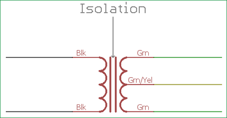
Audio Transformer uses this isolation property and creates isolation between the output speakers or audio circuitry with the transformer’s input side amplifier system. In such case, the primary and secondary winding turns ratio fixed to 1:1. Due to this, the transformer does not alter the voltage or current level. It does only create isolation between the Input amplifiers with the output speaker system.
Other than the isolation transformer there is another audio transformer too, which will change the output voltage level depending on the input AC signal. The loudspeaker is a huge load and needs to provide the required current and voltage across it to produce proper sound vibration. An Audio transformer with Step-up feature will step up the voltage or the current level to drive a load across it. Same happens for the Stepdown transformer too. It converts the voltage from higher to lower with the increased current output.
The audio transformer also provides impedance matching specifications. When the output of one circuit or device is directly connected to the input of another device, it is very important that the device output impedance and device input impedance both are matched. An impedance matching transformer provides this feature and converts higher impedance output to lower impedance to drive a low impedance speaker or feeding to another low impedance device.
Working of Audio Transformer and its Construction
Although an Audio transformer does not have a physical connection between his primary and secondary coil, the transformer provide bidirectional feature between this two windings. We can also use the same primary side as secondary and secondary as primary. In such case, the transformer provides signal loss in one direction and signal gain in reverse direction or vice versa.
The audio transformer works at frequencies between 20 Hz to 20 kHz. So, the operation of an Audio transformer has much wider frequency range.
As discussed above, the audio transformer uses Impedance balancing technique. It is very useful for balancing amplifiers and loads (Loudspeaker and other) that use a different input or output impedances for maximum power transfer application.
In modern days, speakers impedances ranges from 4 to 16 ohms, typically 4 ohms, 8 ohms or 16 ohms speakers are available whereas Transistor or Solid state amplifiers use 200 – 300 ohms output impedance. If the amplifier is a retro design, such as old Valve or Tube amplifier then the output voltage sometimes reach 300V with 3k impedance. We need impedance matching transformer which will convert the High impedance to low impedance and should convert the voltage and current to a level which will directly drive a loudspeaker.
A Transformer can have multiple windings in the primary and secondary side. The ratio between primary and secondary windings, the number of coils turns in the primary side (Np) and a number of coil turns in secondary (Ns) is called the turns ratio. This turns ratio also defines the primary and secondary voltage ratio as the voltage is directly proportional to the primary and secondary winding turns.
So, NP/NS = VP/VS
Audio Transformer Impedance Ratio
Impedance is the most important factor for impedance matching transformers. For impedance matching transformer the impedance ratio between primary to secondary can be calculated using the primary and secondary turn or the primary and secondary output voltage.
To calculate the impedance ratio we need to square the transformer turns ratio or the transformer voltage ratio.
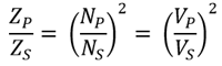
In the above equation, ZP is primary impedance and ZS is secondary impedance. NP/NS is the turns ratio of the transformer and VP/VS is the voltage ratio of the transformer. Impedance ratio is the square of turns ratio or voltage ratio. So, a transformer with 4:1 turns ratio or voltage ratio could provide 16:1 impedance ratio.
Example
We can calculate some practical values depending on the formulas given above.
Suppose, a transformer with a 25:1 turns ratio is used to balance the power amplifier output with a loudspeaker. The Power amplifier provides 100 ohms output impedance, what would be the nominal speaker impedance needed for maximum power transfer?
Solution:
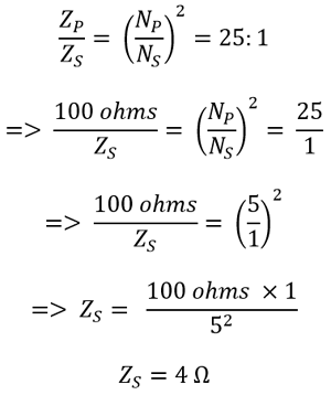
So, using the 25:1 turn’s ratio transformer across 100Ω power amplifier we could efficiently drive 4Ω Loud Speaker with maximum power transfer.
Types of Audio Transformer
As discussed in the above segment, the Audio transformer can be used in multiple applications. But generally, three types of Audio Transformers are mainly used for audio related purposes.
- Impedance matching Transformer
- Step up Audio Transformer with Wide frequency range which is within the audible frequency.
- Step down Audio Transformer with Wide frequency range which is within the audible frequency.
There is another specific Audio transformer also available, which are useful for digital audio applications and generally works in high frequency.
Transformers can also have multiple primary and secondary taps, which provide flexibilities to the user to change the output devices without changing the costly audio transformer. For example, A transformer can have multiple secondary taps to connect multiple loads with 4 ohms, 8 ohms or even 16 ohms impedance but only one tap need to be connected to the load when working with it. Such transformers are generally costly and can be found in retro musical systems or amplifiers.
The transformer can have different bodies depending on where it would be used. A chassis mount transformer needs a supporting chassis to support the bulky weight. Also, there are PCB mounted audio transformers available in various shapes and sizes depending on their specifications and usages.
Microphone Transformer
A microphone transformer mainly used to balance the impedance between Amplifier system and the microphone. It is essential as there will be signal loss due to unbalanced impedance on Amplifier input and microphone output.
A microphone transformer does not reduce Hum noises. A microphone transformer needs a twisted pair with ground shielding wires to connect. The wire consists of two conductors which are tightly twisted together with surrounded by a conducting braid or foil. This wire effectively reduces humming noises and external noise interferences.
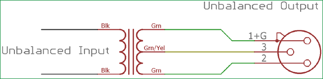
A transformer which have a single primary and receives unbalanced input, and have a center tapped secondary which provides a balanced output, is called as Balun Transformer. In such a configuration, the Amplifier gets a perfect balanced signal.
100V Line Audio Drive Transformer
There are such scenarios where multiple loudspeakers are connected together in long-range public address systems which are connected with a single amplifier system. The problem arrives when long wires are used to connect the Amplifier output and Loudspeaker input. The wire resistance creates trouble for signal quality and the signal loss happens with poor signal amplitude across the speakers.
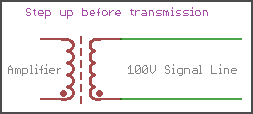
Due to this, two special transformers are used, one is step up and another one is Step Down. The step-up transformer increases the audio output signal voltage to 100V. Due to the Formula P(W) = V x A, when a voltage is increased the current decreases for a given power. The resistance would not effective for the low signal current. The signal will transmit perfectly.
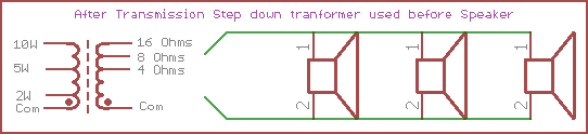
On the other end, across each loudspeaker, a step-down transformer with impedance matching facility, Steps down the 100V to the speaker voltage and increases the current. The Transformer also matches the impedance for maximum power transfer.
This type of audio transformers is called a transmission line matching audio transformer. They have multiple connections in both primary and secondary side. In general, primary side taps are used for suitable power level thus the amplification gain can be controlled by tap connections. And the secondary side has multiple taps which are useful to connect different impedance speakers to different impedance speaker as per choice and availability.
Many modern Professional Amplifier line transformers provide high power handling capabilities as well as multiple configurations to connect parallel or series, loudspeakers together.
