
Transformers generally, are devices capable of converting quantities from one value to the other. For this Article, we will be focusing on the Voltage transformer which is a static electrical component capable of converting AC voltage from one value to the other without changing the frequency using the principles of electromagnetic induction.
In one of our previous articles on the Alternating current, we mentioned how important the transformer was, in the history of the alternating current. It was the major enabler that made the alternating current possible. Initially when DC-based systems were being used, they could not be transferred over long distances due to power loss in the lines as distance (length) increases, which means DC power stations had to be placed everywhere, thus the main goal of AC was to solve the transmission issue and without the transformer, that wouldn't have been possible as the losses would still have existed even with AC.

With the transformer in place, AC could be transmitted from the generating stations at a very high voltage but low current which eliminates the losses in the line(wires) due to the value of I2R (which gives the power loss in a line). The transformer is then used to convert the high voltage, low current energy to Low voltage, high current energy for final distribution within a community without changing the frequency and at the same power that was transmitted from the generating station (P= IV).
To better understand the voltage transformer, it is best to use its most simplified model which is the single-phase transformer.
Single Phase Transformer
The single phase transformer is the most common (in terms of numbers in use) kind of voltage transformers. It is present in most of the “plugged in” appliances we use at home and everywhere else.
It is used to describe the operation principle, construction etc of a transformer because other transformers are like a variation or modification of the single phase transformer. For example, certain people refer to the three-phase transformer as being made up of 3 single phase transformers.
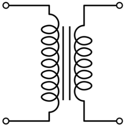
Single Phase Transformer is made up of two coils/winding (The primary and the secondary coil). This two winding are arranged in such a way that there exists no electrical connection between them, thus they are wound around a common magnetic Iron generally referred to as the transformer’s core, thus the two coils only have a magnetic connection between them. This ensures that power is transmitted only via electromagnetic induction and also makes the transformers useful for Isolating connections.
Operational Principle of Transformer:
As earlier mentioned, the transformer consists of two coils; the primary and the secondary coils. The primary coil always represents the input to the transformer while the secondary coil, the output from the transformer.
Two main effects define the operation of the transformer:
The first is that, a current flowing through a wire sets up a magnetic field around the wire. The magnitude of the resulting magnetic field is always directly proportional to the amount of current passing through the wire. The magnitude of the magnetic field is increased, if the wire is wound into a coil-like form. This is the principle with which magnetism is induced by the primary coil. By applying a voltage to the primary coil, it induces a magnetic field around the core of the transformer.
The second effect which when combined with the first explains the operational principle of the transformer which is based on the fact that, if a conductor is wound around a piece of magnet and the magnetic field changes, the change in magnetic field will induce a current in the conductor, the magnitude of which will be determined by the number of turns of the conductor coil. This is the principle with which the secondary coil gets energized.
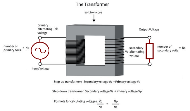
When a voltage is applied to the primary coil, it creates a magnetic field around the core the strength depends on the applied current. The created magnetic field thus induces a current in the secondary coil which is a function of the magnitude of the magnetic field and the numbers of turns of the secondary coil.
This operational principle of the transformer also explains why the AC had to be invented because the transformer will only work when there is an alternation in the applied voltage or current as only then will the electromagnetic induction principles work. Thus the transformer couldn’t be used for DC then.
Construction of the Transformer
Basically, a transformer is made up of two parts which include; two inductive coils and a laminated steel core. The coils are insulated from each other and also insulated to prevent contact with the core.
The construction of the transformer will thus be examined under the coil and core construction.
Transformer’s Core
The core of the transformer is always constructed by stacking laminated sheets of steel together, ensuring a minimum air-gap exists between them. The transformers core in recent times is always made up of laminated steel core instead of iron cores to reduce losses due to eddy current.
There are three major shapes of the laminated steel sheets to choose from, which are E, I, and L.
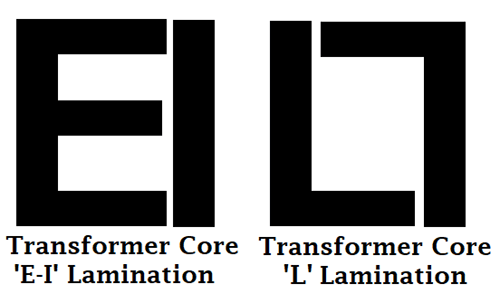
When stacking the lamination together to form the core, they are always stacked in such a way that the sides of the joint are alternated. For example, of the sheets are assembled as front faced during the first assembly, they will be back faced for the next assembly as shown in the image below. This is done to prevent high reluctance at the joints.

Coil
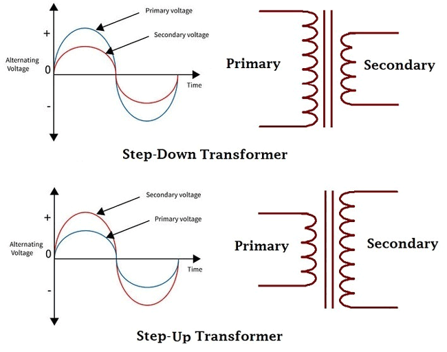
When constructing a transformer, it becomes very important to specify the type of transformer as either step up or step down as this determines the number of turns that will exist in the primary or secondary coil.
Types of Transformers:
Majorly there are three types of voltage transformers;
1. Step Down Transformers
2. Step Up Transformers
3. Isolation Transformers
The step-down transformers are transformers which gives a reduced value of the voltage applied to the primary coil at the secondary coil, while for a step up transformer, the transformer gives an increased value of the voltage applied to the primary coil, at the secondary coil.
Isolation transformers are transformers which gives the same voltage applied to the primary at the secondary and thus basically used to isolate electrical circuits.
From the above explanation, creating a particular type of transformer can only be achieved by designing the number of turns in each of the primary and secondary coils to give the required output, this can thus be determined by the turns ratio. You can read through the linked tutorial to learn more about the different types of transformers.
Transformer Turns Ratio and EMF Equation:
The transformer turns ratio(n) is given by the equation;
n = Np/Ns = Vp/Vs
where n = turns ratio
Np = Number of turns in primary coil
Ns = Number of turns in secondary coil
Vp = Voltage applied to the primary
Vs = Voltage at the secondary
These relationship described above can be used to calculate each of the parameters in the equation.
The formula above is known as the transformers voltage action.
Since we said the power remains the same after transformation then;
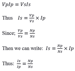
This formula above is referred to as the transformer's current action. Which serves as proof that the transformer not only transforms voltage but also transforms current.
EMF Equation:
The number of turns of the coil of either of the primary or secondary coil determines the amount of current it induces or is induced by it. When the current applied to the primary is reduced, the strength of the magnetic field is reduced and the same for the current induced in the secondary winding.
E = N (dΦ/dt)
The Amount of voltage induced in the secondary winding is given by the equation:
Where N is the number of turns in the secondary winding.
As the flux varies sinusoidally, the magnetic flux Φ = Φmax sinwt
E = N*w*Φmax*cos(wt)
Emax = NwΦmax
The root mean square value of the Induced Emf is gotten by dividing the maximum value of the emf by √2
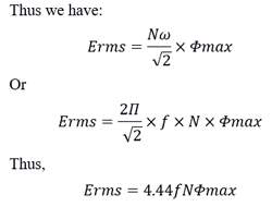
This equation is known as the transformers EMF equation.
Where: N is the number of turns in coil winding
f is the flux frequency in hertz
Φ is the magnetic flux density in Weber
with all these values determined, the transformer can thus be constructed.
Electrical Power
As earlier explained, transformers were created to ensure the value of electrical power generated at the generating stations is delivered to end users with little or no loss, thus in an Ideal transformer, the power at the output(secondary winding) is always the same as the input power. Transformers are thus referred to as constant wattage devices, while they may change the voltage and current values, it's always done in such a way that the same power at the input is available at the output.
Thus
Ps = Pp
where Ps is the power at the secondary and Pp is the power at the primary.
Since P = IvcosΦ
then IsVscosΦs =  IpVpcosΦp
Efficiency of a Transformer
The efficiency of a transformer is given by the equation;
Efficiency = (output power / input power) *100%
While the power output of an Ideal transformer should be the same as the power input, most transformers are far from the Ideal transformer and do experience losses due to several factors.
Some of the losses that can be experienced by a transformer are listed below;
1. Copper Losses
2. Hysteresis losses
3. Eddy current losses
1. Copper Losses
These losses are sometimes referred to as winding losses or I2R losses. These losses are associated with the power dissipated by the conductor used for the winding when current is passed through it due to the resistance of the conductor. The value of this loss can be calculated using the formula;
P = I2R
2. Hysteresis losses
This is a loss related to the reluctance of the materials used for the core of the transformer. As the Alternating current reverses its direction, it has an impact on the internal structure of the material used for the core as it tends to undergo physical changes which also uses up part of the energy
3. Eddy Current Losses
This is a loss typically conquered by the use of laminated thin sheets of steel. The eddy current loss arises from the fact that the core is also a conductor and will induce an emf in the secondary coil. The currents induced in the core according to faradays law will oppose the magnetic field and lead to the dissipation of energy.
Factoring the effect of these losses into the transformer’s efficiency calculations, we have;
Efficiency = (input power - losses / input power )*100%
